Resistance and circuit components

EasyMediumHard
1234567891011121314151617181920212223242526272829303132333435363738394041424344454647484950515253545556575859606162636465
Question 60
Easy

Figure 1 shows the physical components of an electrical circuit used to test a warning system.
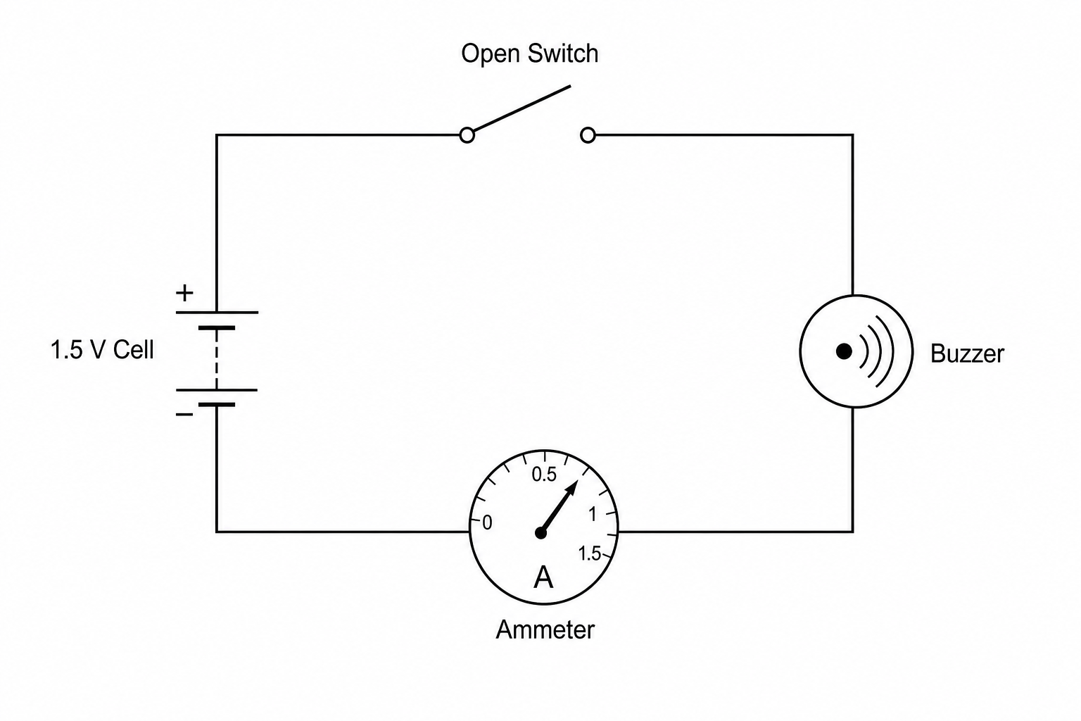
An illustration of a physical circuit containing a 1.5 V cell, an open toggle switch, a circular warning buzzer, and an analog ammeter connected in series with copper wires.

Draw the complete circuit diagram for this circuit.

A single cell symbol and some of the connecting wires have already been drawn for you in Figure 2.
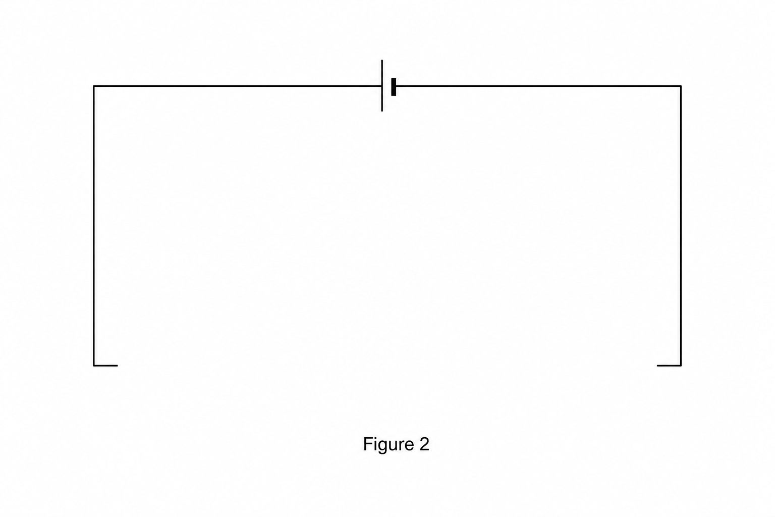
A partial circuit diagram showing a single cell symbol at the top, with lines extending to the left and right to form the top wire of a rectangular circuit loop. The left, bottom, and right sides of the rectangle are incomplete, leaving gaps for the other components.

[4]

Resistance and circuit components Questions

  1. GCSE
  2. /Physics
  3. /Resistance and circuit components