A student carries out an experiment to investigate the electrical resistance of a newly manufactured heating element, Element Ω\OmegaΩ.
The student needs to measure a current of up to 4.5 A4.5\text{ A}4.5 A flowing through the element.
The student has a choice of two different ammeters: Ammeter A and Ammeter B.
The diagram below shows the initial readings on these ammeters before they are connected to any circuit.
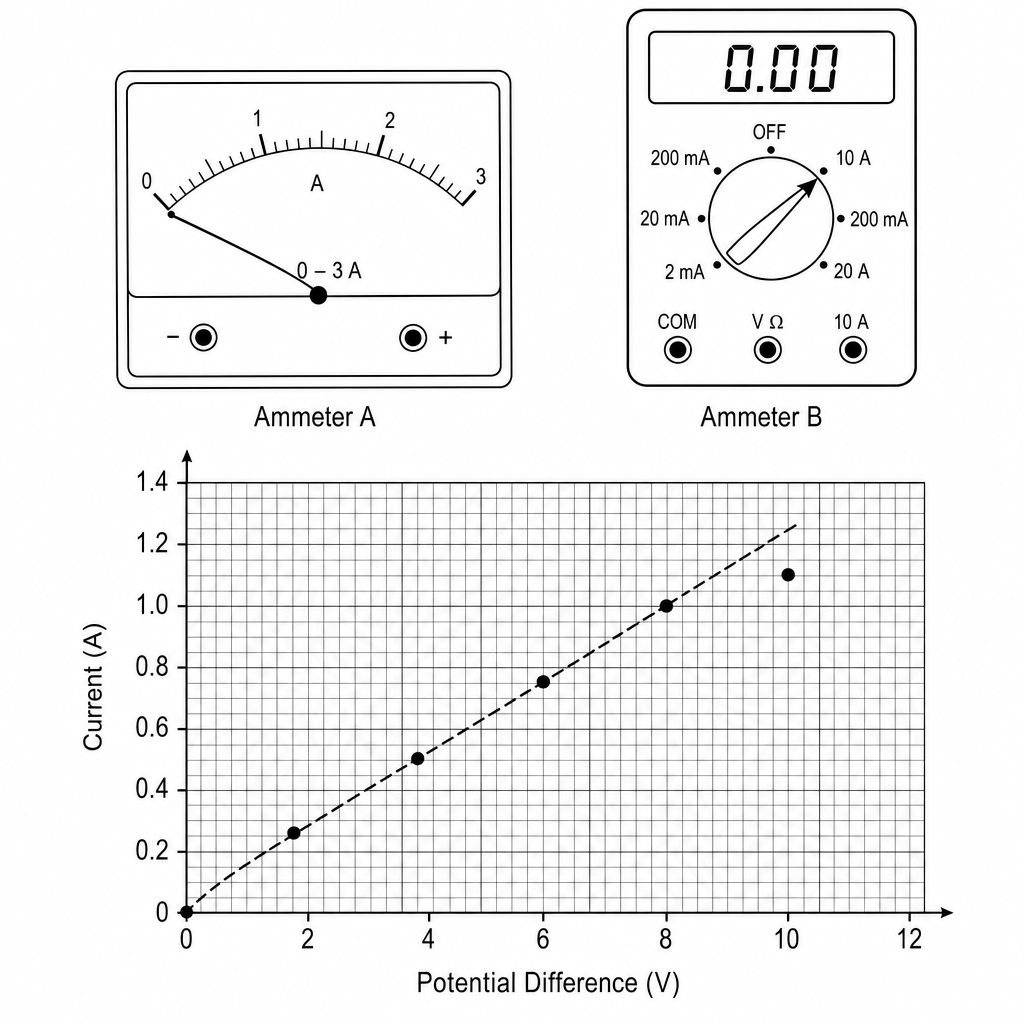
Which ammeter is best for the student to use? Give two reasons.
Ammeter: ‾\underline{\hspace{4cm}}
Reason 1: ‾\underline{\hspace{12cm}}
Reason 2: ‾\underline{\hspace{12cm}}
The student connects the circuit and takes readings of potential difference and current for Element Ω\OmegaΩ. They plot these readings on the graph shown above.
Explain why the student thinks that Element Ω\OmegaΩ behaves as a fixed resistor in the lower voltage region.
The student connects the circuit and takes readings of potential difference and current for Element Ω\OmegaΩ. They plot these readings on the graph shown above.
The student has correctly plotted the point at 10.0 V10.0\text{ V}10.0 V on the graph. Suggest one reason why this point lies below the straight line of best fit.
The student connects the circuit and takes readings of potential difference and current for Element Ω\OmegaΩ. They plot these readings on the graph shown above.
Suggest two ways the student can check if their results are reproducible.
In the linear region of the graph, the resistor has a resistance of 8.0 Ω8.0\ \Omega8.0 Ω.
Calculate the power dissipated by the resistor when the current is 0.75 A0.75\text{ A}0.75 A.
Use the equation: power=(current)2×resistance\text{power} = (\text{current})^2 \times \text{resistance}power=(current)2×resistance