An engineer designs an electrical control circuit as shown in the diagram below.
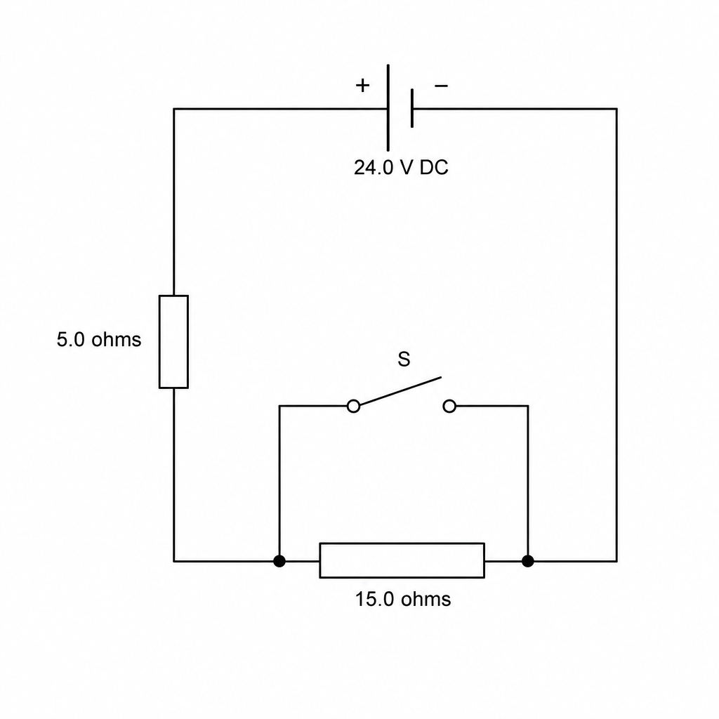
The circuit consists of a constant 24.0 V24.0\text{ V}24.0 V DC power supply connected in series with a 5.0 Ω5.0\ \Omega5.0 Ω resistor and a 15.0 Ω15.0\ \Omega15.0 Ω heating element. A bypass switch SSS is wired in parallel across the heating element.
Calculate the current in the circuit when the switch SSS is open.
State the potential difference across the 5.0 Ω5.0\ \Omega5.0 Ω resistor when the switch SSS is open.
The switch SSS is now closed.
Describe and explain how the current through the 5.0 Ω5.0\ \Omega5.0 Ω resistor changes.
Describe and explain how the potential difference across the 5.0 Ω5.0\ \Omega5.0 Ω resistor changes.
State the potential difference across the heating element when the switch is closed.