A student intends to measure the resistance of a thermistor at room temperature. The thermistor is expected to have a resistance of approximately 150 Ω.
By mistake, the student connects an ideal ammeter and an ideal voltmeter in the circuit shown below, powered by a 9.0 V DC power supply of negligible internal resistance.
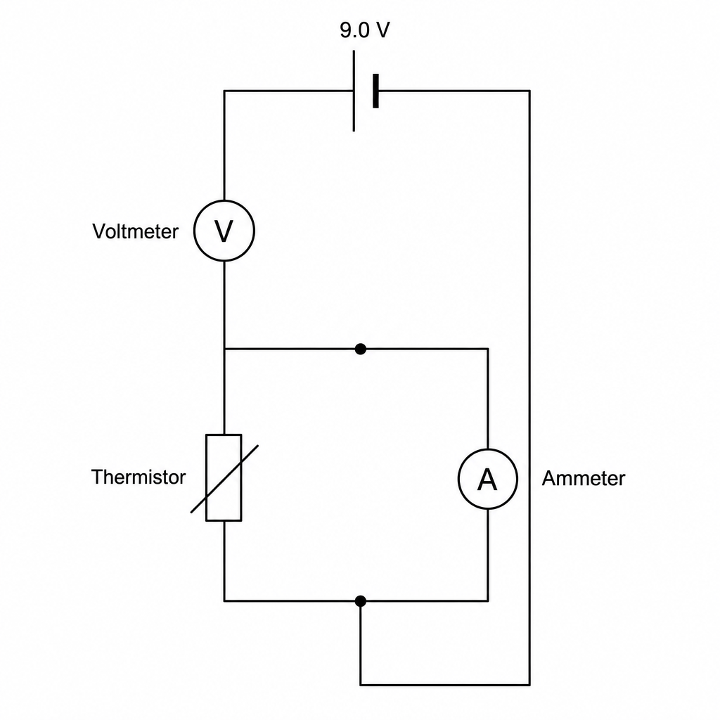
What are the readings on the ammeter and the voltmeter?
Ammeter: 0 A0\text{ A}0 A, Voltmeter: 9.0 V9.0\text{ V}9.0 V
Ammeter: 0.060 A0.060\text{ A}0.060 A, Voltmeter: 9.0 V9.0\text{ V}9.0 V
Ammeter: 0.060 A0.060\text{ A}0.060 A, Voltmeter: 0 V0\text{ V}0 V
Ammeter: 0 A0\text{ A}0 A, Voltmeter: 0 V0\text{ V}0 V