Transformers and the national grid

EasyMediumHard
12345678910111213141516171819202122232425
Question 18
Easy

Figure 1 shows a step-down transformer.
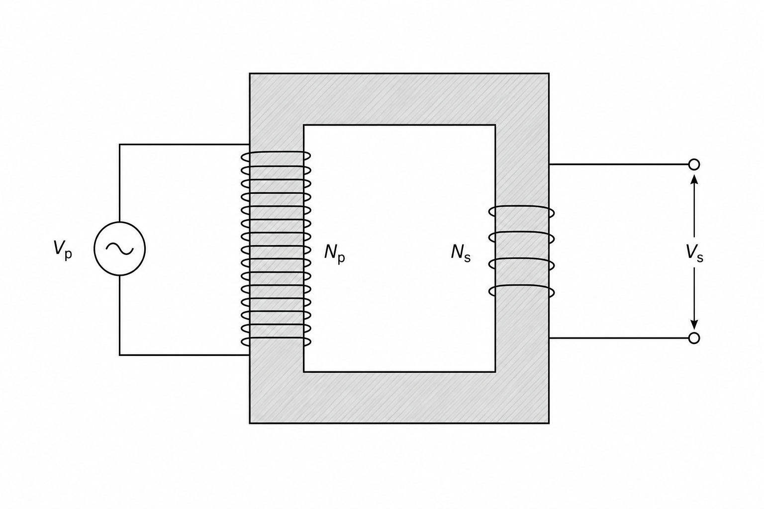
Figure 1: A diagram of a step-down transformer. It features a rectangular laminated iron core with two coils of wire wrapped around opposite sides. On the left side, the input primary coil has N_p turns and is connected to an alternating current supply of potential difference V_p. On the right side, the output secondary coil has N_s turns with a potential difference V_s across it.

The number of turns on the primary coil, Np=1600N_p = 1600Np​=1600

The potential difference across the primary coil, Vp=240 VV_p = 240\text{ V}Vp​=240 V

The number of turns on the secondary coil, Ns=80N_s = 80Ns​=80

Calculate the potential difference across the secondary coil.

[3]

Transformers and the national grid Questions

  1. GCSE
  2. /Physics
  3. /Transformers and the national grid