An alternator is used to generate alternating potential difference (p.d.).
Figure 1 shows a simplified view of a rectangular coil of wire being rotated at a constant speed in a uniform magnetic field.
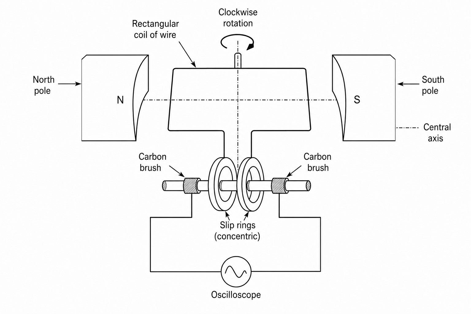
Figure 2 shows how the induced potential difference varies over one complete 360-degree rotation of the coil.
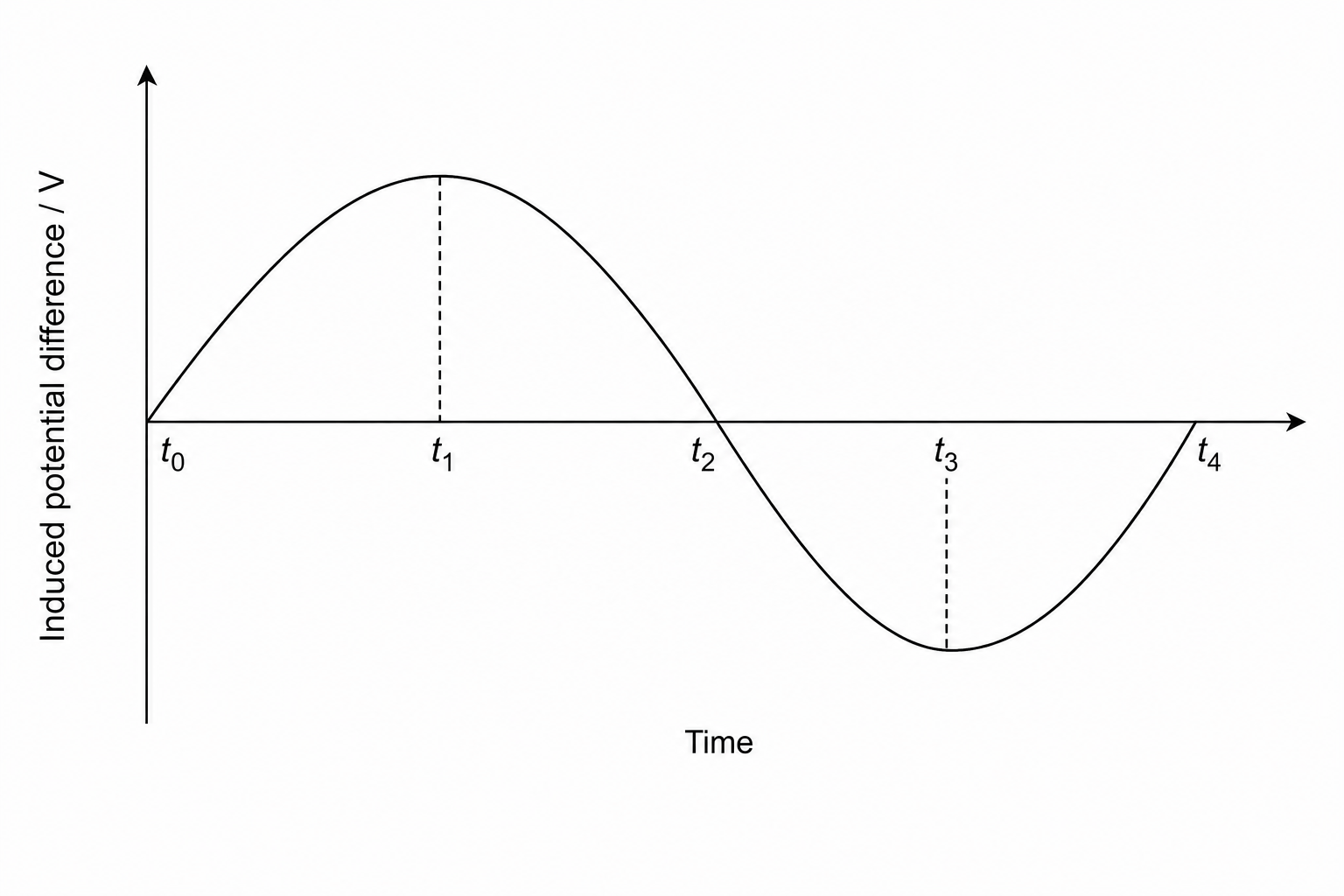
Explain why the induced potential difference varies in the way shown in the graph in Figure 2.
In your explanation, refer to the position and motion of the coil relative to the magnetic field lines at each of the times labelled t0t_0t0, t1t_1t1, t2t_2t2, t3t_3t3, and t4t_4t4.