A micro-hydroelectric generator uses a rotating rectangular coil in a uniform magnetic field to generate electricity.
Figure 1 shows a simplified schematic of the coil of wire rotating at a constant angular velocity in a uniform magnetic field of flux density B⃗\vec{B}B.
Figure 2 shows how the induced electromotive force (e.m.f.), ε\varepsilonε, varies with the angular position of the coil, θ\thetaθ (in radians), over one complete 2π 2\pi\,2π rotation. At θ=0\theta = 0θ=0, the plane of the coil is perpendicular to the magnetic field lines.
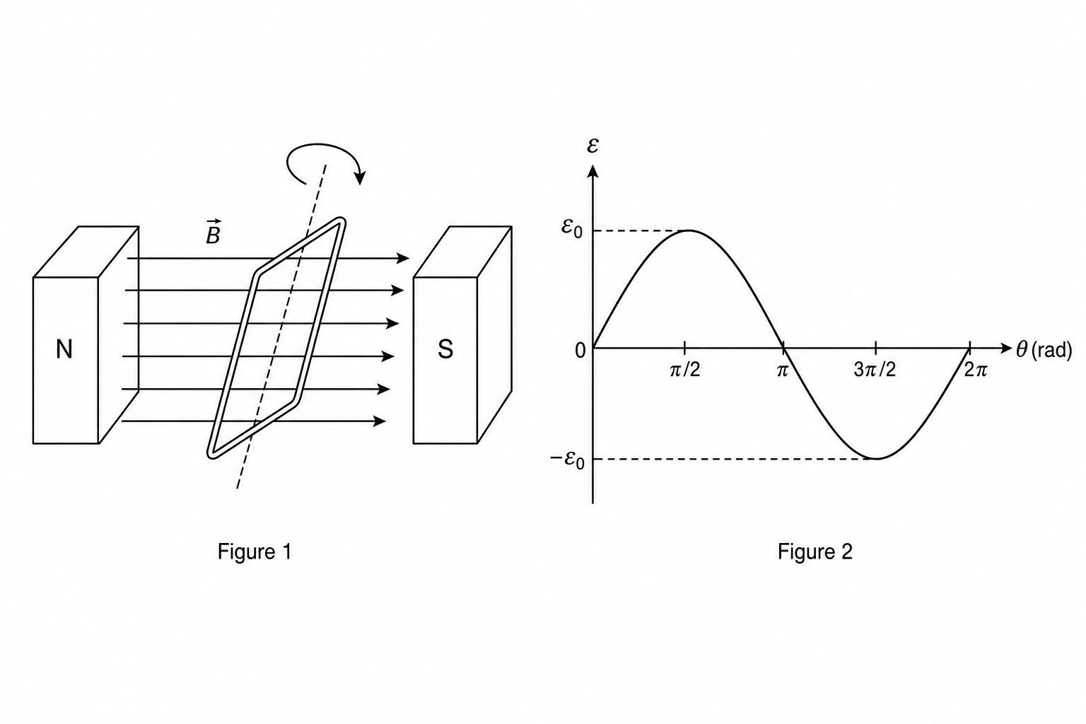
Explain why the induced electromotive force varies in the manner shown in Figure 2.
In your explanation, refer to:
- the magnetic flux linkage through the coil at different angles,
- the rate of cutting of magnetic field lines by the sides of the coil,
- the physical orientation and direction of motion of the coil relative to the magnetic field lines at each of the angular positions: θ=0\theta = 0θ=0, θ=π2\displaystyle \theta = \frac{\pi}{2}θ=2π, θ=π\theta = \piθ=π, θ=3π2\displaystyle \theta = \frac{3\pi}{2}θ=23π, and θ=2π\theta = 2\piθ=2π.