Inducing current, generators and microphones

EasyMediumHard
12345678910111213141516
Question 15
Medium

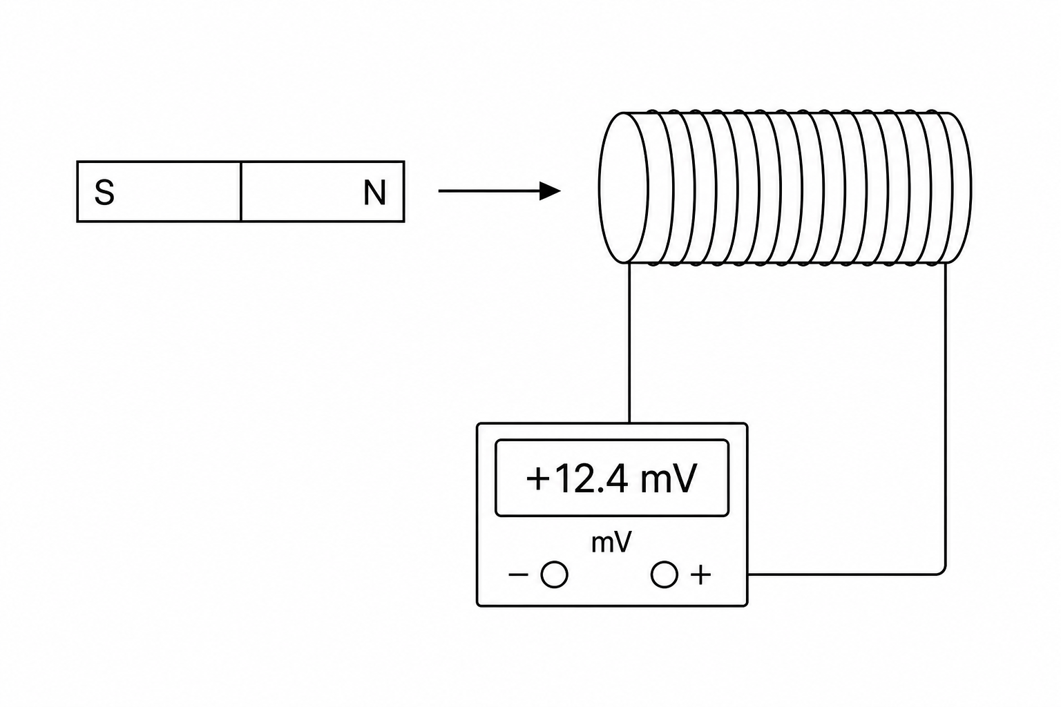
Figure 1 shows a bar magnet being pushed into a coil of wire.

The coil is connected to a sensitive millivoltmeter.

A schematic diagram of an electromagnetic induction experiment. A bar magnet with its North pole facing right is shown next to a horizontal cylindrical coil of wire. An arrow points from the magnet towards the inside of the coil, indicating motion. The two ends of the coil slide down to connect to a digital millivoltmeter which shows a non-zero voltage reading.

Explain why the millivoltmeter shows a reading as the magnet is pushed into the coil.
[3]

Inducing current, generators and microphones Questions

  1. GCSE
  2. /Physics
  3. /Inducing current, generators and microphones