Current electricity

EasyMediumHard
1234567891011121314151617181920212223242526272829303132333435363738394041424344454647484950515253545556575859606162636465666768697071727374757677
Question 48
Medium

A potential divider circuit is constructed using a uniform resistive strip of total resistance 240 Ω240\ \Omega240 Ω between its two ends, A\text{A}A and B\text{B}B. The strip is connected across a battery of emf 6.00 V6.00\text{ V}6.00 V and internal resistance rrr as shown in the diagram.
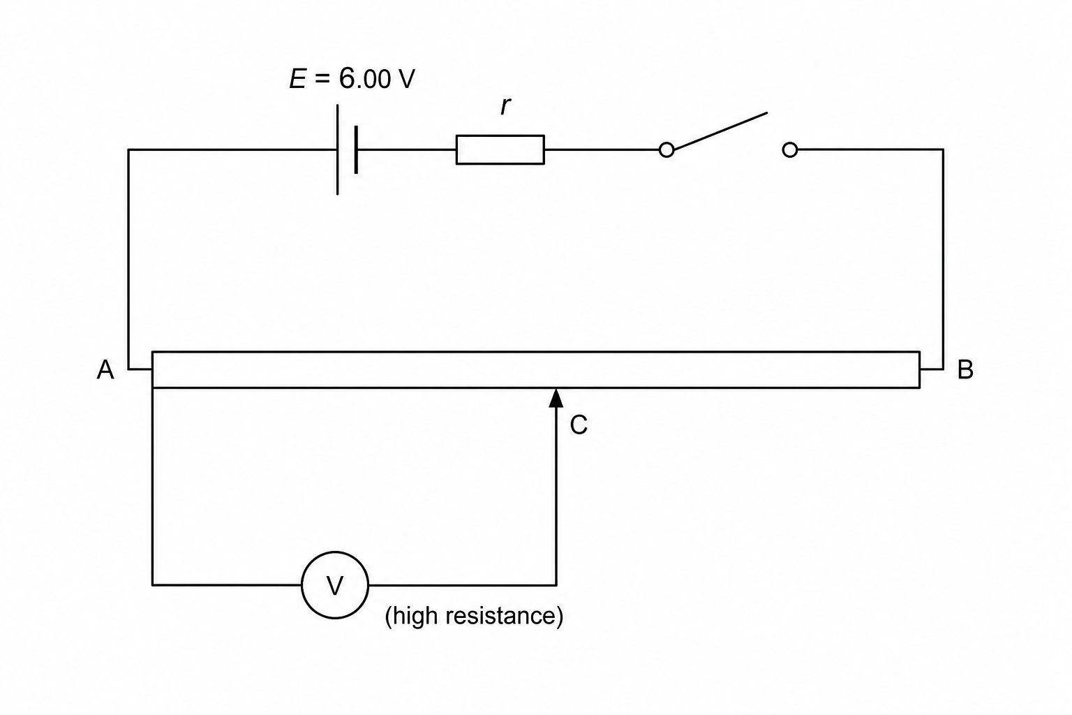
A circuit diagram consisting of a battery of emf 6.00 V and internal resistance r connected in series with a closed switch and a uniform resistive strip AB with total resistance 240 ohms. The negative terminal of the battery is connected directly to terminal A, and the positive terminal is connected to terminal B through the switch. A high-resistance digital voltmeter is connected in parallel between terminal A and a sliding contact C that can position itself anywhere on the strip AB.

1.

When the sliding contact C\text{C}C is moved to end B\text{B}B and the switch is closed, the digital voltmeter reads 5.76 V5.76\text{ V}5.76 V. Calculate the internal resistance rrr of the battery.

[3]
2.

The sliding contact C\text{C}C is then moved to a position that is 14\frac{1}{4}41​ of the distance from A\text{A}A to B\text{B}B, so that the resistance of the strip between A\text{A}A and C\text{C}C is 60.0 Ω60.0\ \Omega60.0 Ω. Determine the reading on the voltmeter at this setting.

[3]

Current electricity Questions

  1. A Level
  2. /Physics
  3. /Current electricity