Current electricity

EasyMediumHard
1234567891011121314151617181920212223242526272829303132333435363738394041424344454647484950515253545556575859606162636465666768697071727374757677
Question 42
Medium

Two circuits, circuit 1 and circuit 2, are used to collect current-voltage data for a lamp. Both circuits use a DC supply with an emf of 15.0 V15.0\text{ V}15.0 V and negligible internal resistance. The current sensor and the voltage sensor behave as ideal meters.
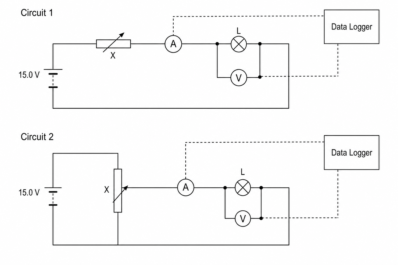
Diagram showing two circuit designs for collecting current-voltage data. Circuit 1 consists of a 15.0 V DC supply in series with a variable resistor X. The variable resistor is in series with an ideal current sensor and a lamp L. An ideal voltage sensor is connected in parallel across the lamp L. Both sensors are connected to a data logger. Circuit 2 consists of the 15.0 V DC supply connected across the outer terminals of a potential divider X. The sliding contact of X is connected in series with the ideal current sensor and the lamp L. The ideal voltage sensor is in parallel across L. Both sensors are connected to the data logger.

In circuit 1:

  • X is used as a simple variable resistor with a maximum resistance of 22.0 Ω22.0\ \Omega22.0 Ω.
  • When X is set to its maximum resistance, the resistance of the lamp L is 3.0 Ω3.0\ \Omega3.0 Ω.

In circuit 2:

  • X is used as a potential divider.

Discuss, with reference to circuit 1 and circuit 2, whether either circuit can produce all the data from a dataset where the lowest recorded data point is at a voltage of 0.80 V0.80\text{ V}0.80 V and a current of 0.35 A0.35\text{ A}0.35 A. Support your answer with a calculation.

[5]

Current electricity Questions

  1. A Level
  2. /Physics
  3. /Current electricity