A materials scientist investigates how the electrical resistance of a newly developed thin-film alloy sensor varies with the potential difference across it.
The experimental setup is shown in the circuit diagram below:
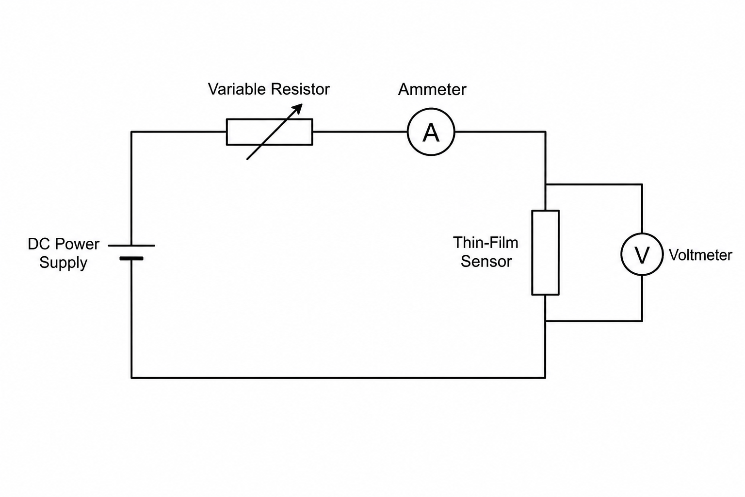
(i) State how the ammeter and the voltmeter are connected in the circuit relative to the thin-film sensor.
(ii) Describe how the scientist should use the variable resistor to obtain a range of current and potential difference readings.
(i) Suggest why it is important to keep the temperature of the thin-film alloy sensor constant during this experiment.
(ii) Describe one practical method the scientist could use to keep the temperature of the sensor constant.
(i) State the relationship linking potential difference, current, and resistance.
(ii) Since the temperature remains constant, the thin-film sensor behaves as an ohmic conductor. Describe the shape of the graph if the scientist plots resistance on the vertical axis against potential difference on the horizontal axis.

