A student investigates how the resistance of a negative temperature coefficient (NTC) thermistor changes with temperature. They measure the current through the thermistor and the voltage across it. The diagram below shows part of the circuit used by the student:
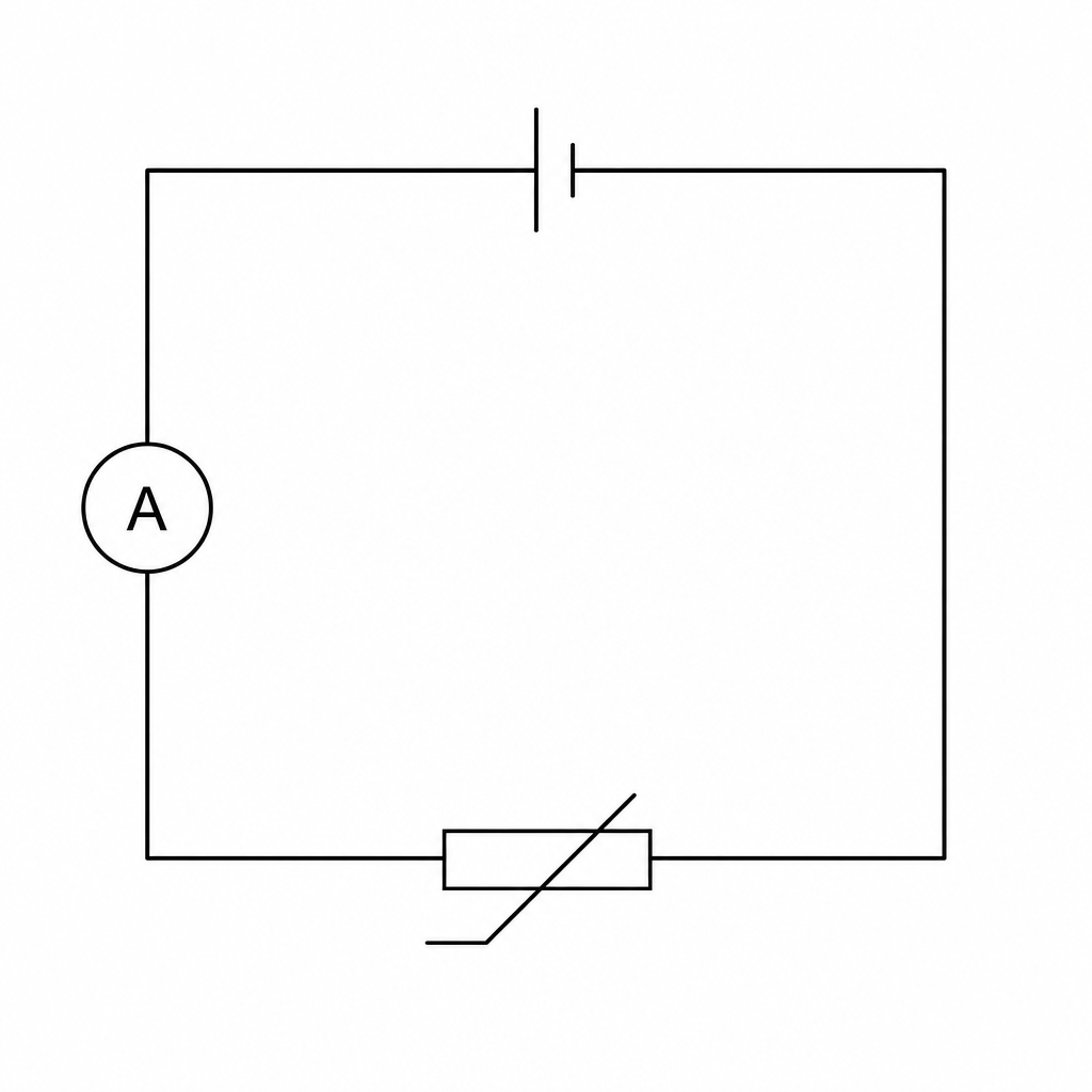
Describe how a voltmeter should be connected to this circuit to measure the potential difference across the thermistor.
Describe the circuit symbol for a voltmeter.
The student varies the temperature of the water bath containing the thermistor and obtains the following results:
| Temperature (°C) | Current (mA) |
|---|---|
| 15 | 0.4 |
| 30 | 1.6 |
| 45 | 4.0 |
| 60 | 8.0 |
| 75 | 16.0 |
State the equation linking voltage, current, and resistance.
The voltage across the thermistor is kept constant at 12.0 V. Calculate the resistance of the thermistor at 30 °C.
Describe how the current in the thermistor changes as temperature increases.
A classmate concludes: "As the temperature increases, the resistance of the thermistor also increases." Evaluate this conclusion using the data from the table.