

What you'll learn
- How to choose and read analogue and digital measuring instruments.
- How to improve accuracy using repeats, timing strategies and alignment aids.
- How to build and check practical circuits, wave experiments and oscilloscope measurements.
- How to use ICT and ionising radiation apparatus safely and sensibly.
The big idea: apparatus is only as good as your technique
In OCR A Physics, practical work is not just “following instructions”. You need to show that you can choose suitable apparatus, use it safely, take measurements carefully, and judge whether the results are reliable.
Apparatus and technique
Apparatus means the equipment you use. A technique is the method used to obtain a valid measurement, such as reading a scale at eye level, timing many oscillations, or checking a circuit before switching on.
A good practical answer often combines three ideas:
- What you measure: for example length, time, current or count rate.
- How you measure it: for example with a ruler, light gate, multimeter or GM tube.
- How you reduce uncertainty: for example repeats, averaging, alignment aids or background subtraction.
Resolution
The resolution of an instrument is the smallest change it can show, such as 1 mm on a ruler, 0.01 mm on a micrometer, or 0.01 V on a digital voltmeter.
Analogue apparatus: reading scales and interpolating
An analogue instrument has a continuous scale, usually with a pointer, liquid column or marked divisions. Examples include:
- metre ruler or tape measure for length and distance
- thermometer for temperature
- pressure gauge or manometer for pressure
- newton meter for force
- protractor for angles
- measuring cylinder, burette or pipette for volume
Interpolation
Interpolation means estimating a value between two scale markings. If a pointer lies between 4.6 N and 4.8 N, you estimate where it is between those marks rather than rounding to the nearest mark automatically.
For analogue scales, you should read with your eye perpendicular to the scale to avoid parallax error, where the reading changes because you are viewing from an angle.
Estimating an analogue reading
A newton meter has scale markings every 0.2 N. The pointer is about 70% of the way from 4.6 N to 4.8 N.
- The interval between the two markings is 4.8−4.6=0.2 N4.8 - 4.6 = 0.2\ \text{N}4.8−4.6=0.2 N.
- The pointer is 70% of this interval above 4.6 N, so the extra amount is 0.70×0.2 N=0.14 N0.70 \times 0.2\ \text{N} = 0.14\ \text{N}0.70×0.2 N=0.14 N.
- The estimated force is therefore 4.6 N+0.14 N=4.74 N4.6\ \text{N} + 0.14\ \text{N} = 4.74\ \text{N}4.6 N+0.14 N=4.74 N, which should sensibly be recorded as about 4.7 N or 4.74 N depending on the scale quality.
- A reasonable reading uncertainty is about half the smallest division, so ±0.1 N\pm 0.1\ \text{N}±0.1 N.
Parallax when reading scales
Do not read a thermometer, ruler, protractor or meter scale from the side. Put your eye level with the marker or meniscus and perpendicular to the scale.
Digital instruments and multimeters
A digital instrument gives a numerical reading directly. Examples include digital stopwatches, digital balances, electronic thermometers, data loggers and digital multimeters.
Digital multimeter
A digital multimeter is an instrument that can measure electrical quantities such as potential difference in volts, current in amperes and resistance in ohms, depending on the selected setting and connections.
Digital instruments avoid interpolation, but they still have uncertainty. A common starting point is the resolution: if a balance reads to 0.01 g, readings change in steps of 0.01 g.
When using a multimeter:
- choose the correct quantity: current, voltage or resistance
- choose a range larger than the expected value
- connect current meters in series and voltage meters in parallel
- check polarity if using a DC circuit
- never measure resistance in a powered circuit
Choosing a meter range
Start on the highest suitable range if you are unsure. Then move down to get more decimal places without overloading the meter.
Increasing accuracy: repeats, alignment aids and better timing
Accuracy means closeness to the true value. Precision means how closely repeated readings agree with each other. A practical method can improve both.
Useful techniques include:
- taking repeat readings and calculating a mean
- timing many oscillations rather than one
- using a fiducial marker, which is a fixed reference mark used to judge a position consistently
- using a set square to make a perpendicular measurement
- using a plumb line to define the vertical
- using light gates instead of human reaction timing
Measure a bigger interval when possible
If the uncertainty in starting and stopping a timer is roughly fixed, timing a longer total interval makes the percentage uncertainty smaller.
Timing multiple oscillations
A student times 20 oscillations of a pendulum as 31.6 s. The estimated timing uncertainty for the whole interval is ±0.2 s.
- Calculate the period using total time divided by the number of oscillations:
T=31.6 s20=1.58 sT = \frac{31.6\ \text{s}}{20} = 1.58\ \text{s}T=2031.6 s=1.58 s. - Divide the absolute timing uncertainty by the same number of oscillations:
ΔT=0.2 s20=0.01 s\Delta T = \frac{0.2\ \text{s}}{20} = 0.01\ \text{s}ΔT=200.2 s=0.01 s. - The period is therefore T=1.58±0.01 sT = 1.58 \pm 0.01\ \text{s}T=1.58±0.01 s.
- The percentage uncertainty is 0.011.58×100%≈0.63%\frac{0.01}{1.58} \times 100\% \approx 0.63\%1.580.01×100%≈0.63%.
A stopwatch is simple but includes reaction time. Light gates are better when an object passes a known point: the gate starts or stops timing automatically as a beam is blocked.
Calipers and micrometers for small distances
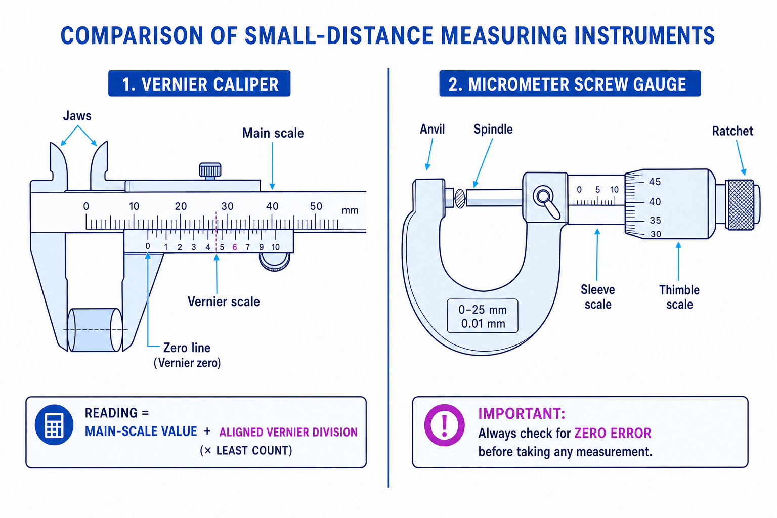
For small distances, a ruler is often not precise enough. You may use:
- vernier calipers for external diameter, internal diameter or depth
- micrometer screw gauges for very small thicknesses or diameters, such as a wire
The diagram shows the main parts you should recognise and the basic reading idea.
Zero error
A zero error occurs when an instrument does not read zero when it should. You correct for it by subtracting the zero reading from the measured reading.
Correcting a micrometer reading
A micrometer reads 2.87 mm when measuring a wire. When fully closed, it reads +0.03 mm instead of zero.
- Identify the zero error: the micrometer is already reading 0.03 mm too high.
- Correct the measurement by subtracting the positive zero error:
corrected diameter =2.87 mm−0.03 mm= 2.87\ \text{mm} - 0.03\ \text{mm}=2.87 mm−0.03 mm. - The corrected diameter is 2.84 mm2.84\ \text{mm}2.84 mm.
- In SI units, this is 2.84×10⁻³ m2.84 \times 10^{-3}\ \text{m}2.84×10⁻³ m.
Crushing the object
With a micrometer, use the ratchet rather than forcing the thimble. Over-tightening can squash soft materials and give a diameter that is too small.
DC circuits: constructing, designing and checking
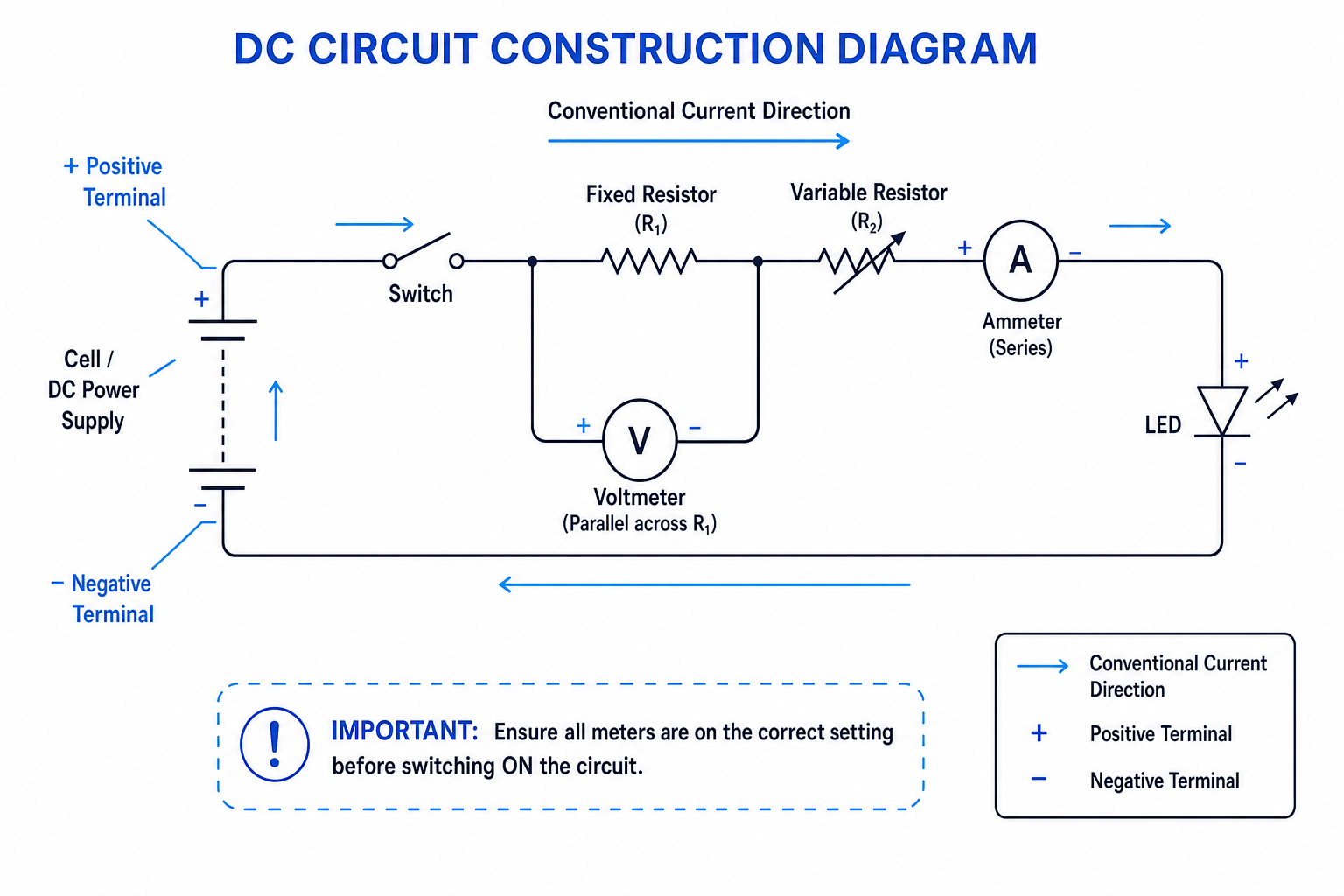
For circuit practicals, you must be able to build circuits from diagrams using cells, DC power supplies, resistors, lamps, switches, diodes, LEDs and meters. Some components have polarity, meaning they must be connected the correct way round.
The key meter rules are:
- ammeter in series with the component
- voltmeter in parallel across the component
- positive meter terminal towards the positive side of the supply
- switch open while constructing and checking
Check before switching on
Before turning on a DC supply, check for short circuits, correct meter ranges, correct polarity for diodes and LEDs, and that the current limit or supply voltage is sensible.
Designing a circuit means thinking ahead: what is the independent variable, what is the dependent variable, and which quantities must be controlled? For example, in an I–V experiment you might vary the potential difference and measure the current through a component.
Signal generators and oscilloscopes
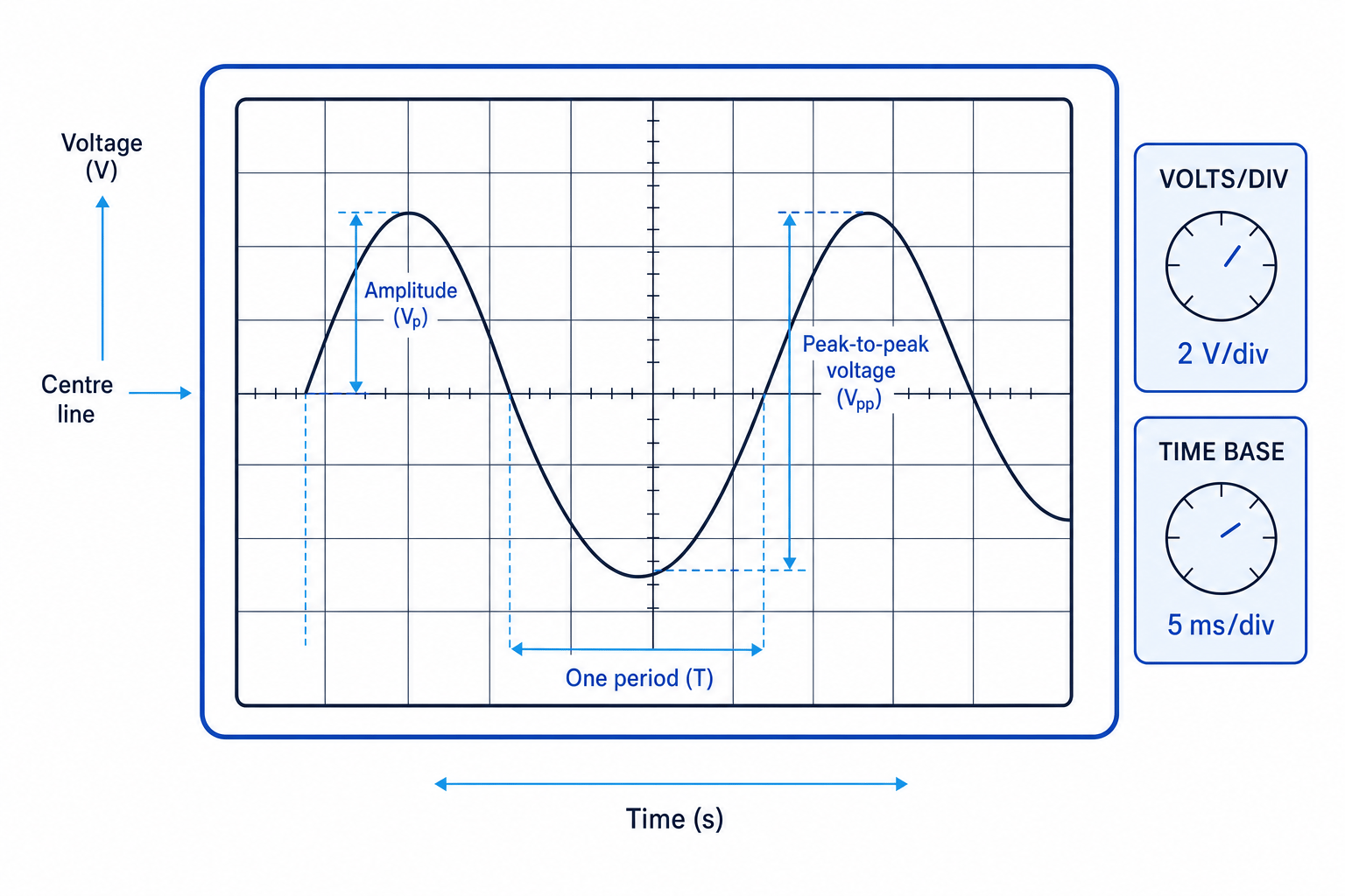
A signal generator produces an alternating electrical signal with adjustable frequency and amplitude. An oscilloscope displays potential difference against time.
Volts per division and time-base
The volts/division setting tells you the vertical scale of the oscilloscope screen. The time-base tells you the horizontal time scale, usually in seconds per division or milliseconds per division.
Finding amplitude and frequency from an oscilloscope trace
An oscilloscope trace has a peak-to-peak height of 4.0 divisions. The volts/division setting is 2.0 V/div. One full cycle takes 5.0 divisions, and the time-base is 5.0 ms/div.
- Calculate the peak-to-peak potential difference:
Vpp=4.0×2.0 V=8.0 VV_{pp} = 4.0 \times 2.0\ \text{V} = 8.0\ \text{V}Vpp=4.0×2.0 V=8.0 V. - The amplitude is half the peak-to-peak value:
amplitude =8.0 V2=4.0 V= \frac{8.0\ \text{V}}{2} = 4.0\ \text{V}=28.0 V=4.0 V. - Calculate the period:
T=5.0×5.0 ms=25 ms=2.5×10⁻² sT = 5.0 \times 5.0\ \text{ms} = 25\ \text{ms} = 2.5 \times 10^{-2}\ \text{s}T=5.0×5.0 ms=25 ms=2.5×10⁻² s. - Calculate frequency using f=1Tf = \frac{1}{T}f=T1:
f=12.5×10⁻² s=40 Hzf = \frac{1}{2.5 \times 10^{-2}\ \text{s}} = 40\ \text{Hz}f=2.5×10⁻² s1=40 Hz.
Generating and measuring waves
Different wave experiments use different sources and detectors:
- sound waves: loudspeaker and microphone
- water waves: ripple tank, lamp and screen
- vibrations: vibration transducer or signal generator
- microwaves or radio waves: transmitter and receiver
You often measure frequency fff, wavelength λ\lambdaλ and wave speed vvv, linked by:
v=fλv = f\lambdav=fλCalculating wave speed in a ripple tank
A ripple tank source has frequency 12 Hz. The distance across 10 wavelengths is measured as 0.350 m.
- Find one wavelength by dividing the total distance by 10:
λ=0.350 m10=0.0350 m\lambda = \frac{0.350\ \text{m}}{10} = 0.0350\ \text{m}λ=100.350 m=0.0350 m. - Use the wave equation:
v=fλv = f\lambdav=fλ. - Substitute the values:
v=12 Hz×0.0350 m=0.420 m s−1v = 12\ \text{Hz} \times 0.0350\ \text{m} = 0.420\ \text{m s}^{-1}v=12 Hz×0.0350 m=0.420 m s−1.
Light, interference and diffraction
A laser or suitable light source can be used to investigate interference and diffraction. A laser is useful because it produces a narrow, intense beam with one main wavelength.
Good technique includes:
- never looking directly into the laser beam
- aligning the laser, slit or grating, and screen carefully
- measuring across many fringes, then dividing by the number of fringe spacings
- keeping the screen distance large enough for measurable fringe spacing
Measuring one tiny fringe spacing
Do not measure just one fringe spacing if several are visible. Measure across many bright fringes and divide; this reduces percentage uncertainty.
ICT: sensors, data loggers, modelling and software
ICT can improve practical work when used thoughtfully. A data logger records readings from sensors such as light gates, temperature probes, pressure sensors, microphones or motion sensors.
Software may be used to:
- collect many readings quickly
- plot graphs
- calculate gradients and intercepts
- model a physical situation
- process data using a spreadsheet
ICT is not automatically better
A sensor still needs calibration, an appropriate sampling rate and a suitable range. A beautiful graph from bad data is still bad evidence.
Ionising radiation and detectors
Ionising radiation has enough energy to remove electrons from atoms. Practical work may involve sealed sources and detectors such as a Geiger–Müller tube connected to a counter or ratemeter.
Safe technique follows three principles:
- minimise time near the source
- maximise distance from the source
- use suitable shielding and handling tools
You also need to measure background radiation, which is the count recorded even when the source is not present.
Correcting a radiation count rate
A detector records 246 counts in 60 s with a source present. Background radiation is measured as 36 counts in 60 s.
- Calculate the source-plus-background count rate:
24660 s=4.10 s−1\frac{246}{60\ \text{s}} = 4.10\ \text{s}^{-1}60 s246=4.10 s−1. - Calculate the background count rate:
3660 s=0.60 s−1\frac{36}{60\ \text{s}} = 0.60\ \text{s}^{-1}60 s36=0.60 s−1. - Subtract the background rate:
corrected count rate =4.10 s−1−0.60 s−1=3.50 s−1= 4.10\ \text{s}^{-1} - 0.60\ \text{s}^{-1} = 3.50\ \text{s}^{-1}=4.10 s−1−0.60 s−1=3.50 s−1. - Quote the corrected count rate as 3.5 s−13.5\ \text{s}^{-1}3.5 s−1 to a sensible number of significant figures.
In the exam
- Name the apparatus and the technique: for example “use a light gate to avoid reaction-time uncertainty”, not just “measure the time”.
- Link improvements to uncertainty: say whether you are reducing parallax, reaction time, zero error, random variation or percentage uncertainty.
- For circuits and radiation, include safety checks: correct polarity/ranges for circuits, and time–distance–shielding plus background count for radiation.
Check yourself
- Why does timing 20 oscillations usually give a better period than timing one oscillation?
- How should an ammeter and voltmeter be connected in a DC circuit?
- Why must background radiation be measured before using a radioactive source?
