

What you'll learn
- How two series components share an input potential difference.
- How to use Vout=R2R1+R2VinV_{\text{out}} = \frac{R_2}{R_1 + R_2}V_{\text{in}}Vout=R1+R2R2Vin and V1V2=R1R2\frac{V_1}{V_2} = \frac{R_1}{R_2}V2V1=R2R1.
- How a potentiometer gives a continuously variable output voltage.
- How LDRs and thermistors can be used to make light- and temperature-sensing circuits.
The basic idea: sharing voltage in series
Before potential dividers, you need one key rule about series circuits: the same current passes through every component in the loop.
A potential difference is the energy transferred per unit charge between two points in a circuit, measured in volts (V). A resistor with a larger resistance gets a larger share of the supply potential difference, because V=IRV = IRV=IR and the current is the same through each series resistor.
Potential divider
A potential divider is a circuit with components in series across an input potential difference, arranged so that a chosen fraction of the input potential difference is obtained as an output potential difference.
In the standard two-resistor divider, the input voltage VinV_{\text{in}}Vin is across both resistors. The output voltage VoutV_{\text{out}}Vout is often measured across the lower resistor, labelled R2R_2R2.
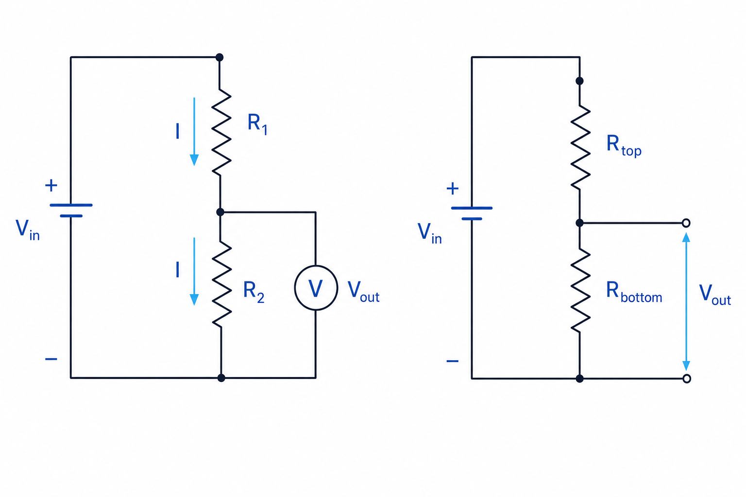
Deriving the potential divider equations
For two resistors in series, the total resistance is:
Rtotal=R1+R2R_{\text{total}} = R_1 + R_2Rtotal=R1+R2The current in the circuit is:
I=VinR1+R2I = \frac{V_{\text{in}}}{R_1 + R_2}I=R1+R2VinThe output voltage across R2R_2R2 is then:
Vout=IR2=VinR1+R2R2\begin{aligned} V_{\text{out}} &= IR_2 \\ &= \frac{V_{\text{in}}}{R_1 + R_2}R_2 \end{aligned}Vout=IR2=R1+R2VinR2So the potential divider equation is:
Vout=R2R1+R2VinV_{\text{out}} = \frac{R_2}{R_1 + R_2}V_{\text{in}}Vout=R1+R2R2VinBecause the current is the same through both resistors, the voltage ratio matches the resistance ratio:
V1V2=R1R2\frac{V_1}{V_2} = \frac{R_1}{R_2}V2V1=R2R1The voltage share rule
In a series potential divider, a component gets the same fraction of the input voltage as its fraction of the total series resistance.
Calculating the output voltage
A potential divider has R1=2.2 kΩR_1 = 2.2 \text{ k}\OmegaR1=2.2 kΩ, R2=3.3 kΩR_2 = 3.3 \text{ k}\OmegaR2=3.3 kΩ, and Vin=9.0 VV_{\text{in}} = 9.0 \text{ V}Vin=9.0 V. Find VoutV_{\text{out}}Vout across R2R_2R2.
- Choose the correct resistance for the numerator. Since VoutV_{\text{out}}Vout is across R2R_2R2, use R2R_2R2 in the fraction:
- Substitute the values, keeping both resistances in the same unit:
- Calculate the fraction of the input voltage:
Using the wrong resistor in the numerator
The numerator is the resistance across which the output voltage is measured. If VoutV_{\text{out}}Vout is across R2R_2R2, use R2R_2R2. If it is across R1R_1R1, use R1R_1R1.
Designing a divider for a required output
Sometimes you choose resistor values to give a particular output voltage. A useful rearrangement comes from thinking in ratios.
If the supply is split into V1V_1V1 across R1R_1R1 and V2V_2V2 across R2R_2R2, then:
V1V2=R1R2\frac{V_1}{V_2} = \frac{R_1}{R_2}V2V1=R2R1So, for example, if the top resistor needs twice the voltage of the bottom resistor, it should have twice the resistance.
Choosing a resistor for a required output
A 12.0 V supply is used in a divider. The output is taken across a 2.0 kΩ2.0 \text{ k}\Omega2.0 kΩ lower resistor. Choose the upper resistor so that Vout=4.0 VV_{\text{out}} = 4.0 \text{ V}Vout=4.0 V.
- Work out the voltage across the upper resistor:
- Use the voltage ratio to find the resistance ratio:
- Calculate the upper resistor:
Potentiometers as potential dividers
A potentiometer is a three-terminal variable resistor. It has a resistive track and a sliding contact called a wiper.
When the supply is connected across the two ends of the track, the wiper taps off a chosen fraction of the input voltage. Moving the wiper changes the ratio of the resistance above and below it, so VoutV_{\text{out}}Vout can vary smoothly from about 0 V up to about VinV_{\text{in}}Vin.
Potentiometer
A potentiometer is a variable potential divider with three terminals: two ends of a resistive track and one sliding wiper contact.
Potentiometer versus variable resistor
Using all three terminals makes a potentiometer act as a potential divider. Using only two terminals makes it act like a variable resistor controlling current.
Variable components in potential dividers
Potential dividers become especially useful when one resistor changes with the environment.
An LDR, or light-dependent resistor, has a resistance that decreases as light intensity increases.
A thermistor is a resistor whose resistance changes with temperature. At A Level, the usual thermistor is an NTC thermistor: its resistance decreases as temperature increases.
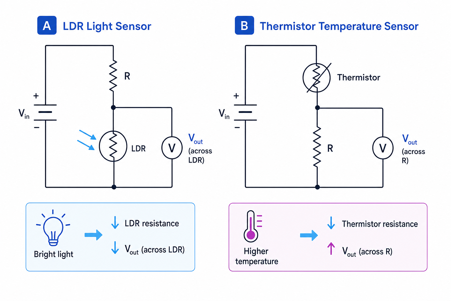
The output depends on where the sensor is placed and where VoutV_{\text{out}}Vout is measured.
If the variable component is the lower resistor
If VoutV_{\text{out}}Vout is measured across the lower component, then:
Vout=RlowerRupper+RlowerVinV_{\text{out}} = \frac{R_{\text{lower}}}{R_{\text{upper}} + R_{\text{lower}}}V_{\text{in}}Vout=Rupper+RlowerRlowerVinSo if the lower resistance decreases, VoutV_{\text{out}}Vout decreases.
For an LDR placed as the lower resistor, brighter light gives lower resistance, so the output voltage decreases.
If the variable component is the upper resistor
If the sensor is the upper resistor but VoutV_{\text{out}}Vout is measured across the fixed lower resistor, then a decrease in the sensor resistance makes the fixed resistor a larger fraction of the total resistance.
So for an NTC thermistor placed above a fixed lower resistor, higher temperature gives lower thermistor resistance, so VoutV_{\text{out}}Vout across the fixed resistor increases.
Predicting how a sensor output changes
An NTC thermistor is the upper resistor in a potential divider. A fixed resistor is the lower resistor, and VoutV_{\text{out}}Vout is measured across the fixed resistor. What happens to VoutV_{\text{out}}Vout when the temperature increases?
-
Identify how the thermistor changes: for an NTC thermistor, increasing temperature decreases its resistance.
-
Compare the fixed lower resistor with the new total resistance. The lower resistor stays the same, but the total Rthermistor+RfixedR_{\text{thermistor}} + R_{\text{fixed}}Rthermistor+Rfixed decreases.
-
Apply the divider fraction:
Since the denominator decreases while the numerator stays the same, VoutV_{\text{out}}Vout increases.
Assuming every sensor output rises
An LDR or thermistor resistance may decrease, but the output voltage might increase or decrease depending on whether the sensor is above or below the output point.
Choosing component positions for sensing circuits
For sensing circuits, decide what you want the output voltage to do.
If you want VoutV_{\text{out}}Vout to increase when light intensity increases, place the LDR as the upper resistor and measure the output across the fixed lower resistor.
If you want VoutV_{\text{out}}Vout to decrease when light intensity increases, place the LDR as the lower resistor and measure the output across it.
The same logic applies to an NTC thermistor:
- Thermistor lower, output across thermistor: higher temperature gives lower VoutV_{\text{out}}Vout.
- Thermistor upper, output across fixed lower resistor: higher temperature gives higher VoutV_{\text{out}}Vout.
A good fixed resistor value is often similar to the sensor resistance near the temperature or light level where you want the circuit to be most responsive. This makes the output voltage change noticeably around the useful range.
Practical investigation of a potential divider
To investigate a potential divider, you normally build the circuit, vary one physical quantity, and measure the output potential difference with a voltmeter or data logger.
For a thermistor investigation:
- Use a low-voltage direct-current supply.
- Put the thermistor in a water bath with a thermometer.
- Stir the water and allow the thermistor reading to settle before recording.
- Measure VoutV_{\text{out}}Vout at different temperatures.
- Keep VinV_{\text{in}}Vin constant throughout.
For an LDR investigation:
- Use a lamp or phone torch at measured distances, or use a light meter if available.
- Shield the LDR from background light as much as possible.
- Keep the orientation of the LDR and lamp fixed.
- Measure VoutV_{\text{out}}Vout for different light intensities.
You can then plot a graph of output voltage against temperature or light intensity. The graph may not be a straight line, because LDRs and thermistors do not usually have linear resistance changes.
Loading the potential divider
The simple divider equations assume the output is measured by a very high-resistance device, such as a voltmeter, so that negligible current is drawn from the output. If a low-resistance load is connected across the output, it changes the effective resistance and the output voltage.
Finding resistance from a measured output
A thermistor is the lower component in a divider with a 4.7 kΩ4.7 \text{ k}\Omega4.7 kΩ fixed upper resistor. The supply is 6.0 V6.0 \text{ V}6.0 V. At one temperature, VoutV_{\text{out}}Vout across the thermistor is 2.0 V2.0 \text{ V}2.0 V. Find the thermistor resistance.
- Start from the divider equation with the thermistor as the lower resistor:
- Substitute the known values:
- Divide both sides by 6.0 V6.0 \text{ V}6.0 V and rearrange:
- Solve for the thermistor resistance:
To two significant figures, RT=2.4 kΩR_T = 2.4 \text{ k}\OmegaRT=2.4 kΩ.
Final checklist for the method
When you see a potential divider question:
- Mark the input voltage across the whole series combination.
- Mark exactly where the output voltage is measured.
- Put the output resistance in the numerator.
- Put the total series resistance in the denominator.
- Think physically: larger share of resistance means larger share of voltage.
In the exam
- Draw or annotate the circuit before calculating; most mistakes come from choosing the wrong output component.
- For LDRs and thermistors, state the resistance change first, then use the divider equation to decide the voltage change.
- In practical questions, mention controlling VinV_{\text{in}}Vin, using a voltmeter or data logger, repeating readings, and reducing unwanted heating or background light.
Check yourself
- If R2R_2R2 is doubled while R1R_1R1 and VinV_{\text{in}}Vin stay fixed, what happens to VoutV_{\text{out}}Vout across R2R_2R2?
- How would you arrange an LDR divider so that the output voltage rises in brighter light?
- Why does connecting a low-resistance load across the output change the divider behaviour?

