

What you'll learn
- What a source of e.m.f. is, and why real sources are not perfect.
- How internal resistance causes “lost volts” inside a cell or power supply.
- How to use E=I(R+r)E = I(R + r)E=I(R+r) and E=V+IrE = V + IrE=V+Ir in calculations.
- How to determine internal resistance experimentally from a VVV against III graph.
The prerequisite ideas
Before internal resistance, you need three circuit quantities to feel secure.
Current, potential difference and resistance
- Current, III, is the rate of flow of charge. It is measured in amperes, A.
- Potential difference, VVV, is the energy transferred per unit charge between two points. It is measured in volts, V.
- Resistance, RRR, tells you how difficult it is for current to flow through a component. It is measured in ohms, Ω.
For an ohmic resistor at constant temperature, OCR uses:
V=IRV = IRV=IRSo if a current flows through a resistance, there is a potential difference across it. That simple idea is the key to “lost volts” later.
Sources of e.m.f.
A source of e.m.f. is any device that transfers energy to charges in a circuit. Examples include a chemical cell, a battery, a solar cell, or a power supply.
Electromotive force
The electromotive force, e.m.f. EEE, of a source is the energy transferred from other forms to electrical energy per unit charge passing through the source. It is measured in volts, V.
Despite the name, e.m.f. is not a force. It is an energy-per-charge quantity.
For example, a 1.50 V cell transfers 1.50 joules of energy to each coulomb of charge passing through it, before any energy losses inside the cell are considered.
E.m.f. is energy supplied per charge
A source of e.m.f. uses a non-electrical energy store, such as chemical energy, to do work on charges and drive them around the circuit.
Internal resistance
Real cells and power supplies are not perfect. They contain materials inside them, so charges experience some opposition to flow before they even reach the external circuit.
Internal resistance
The internal resistance, rrr, of a source is the resistance inside the source itself. It is measured in ohms, Ω.
We model a real cell as:
- an ideal source of e.m.f. EEE
- in series with an internal resistor rrr
The external circuit then has a load resistance RRR.
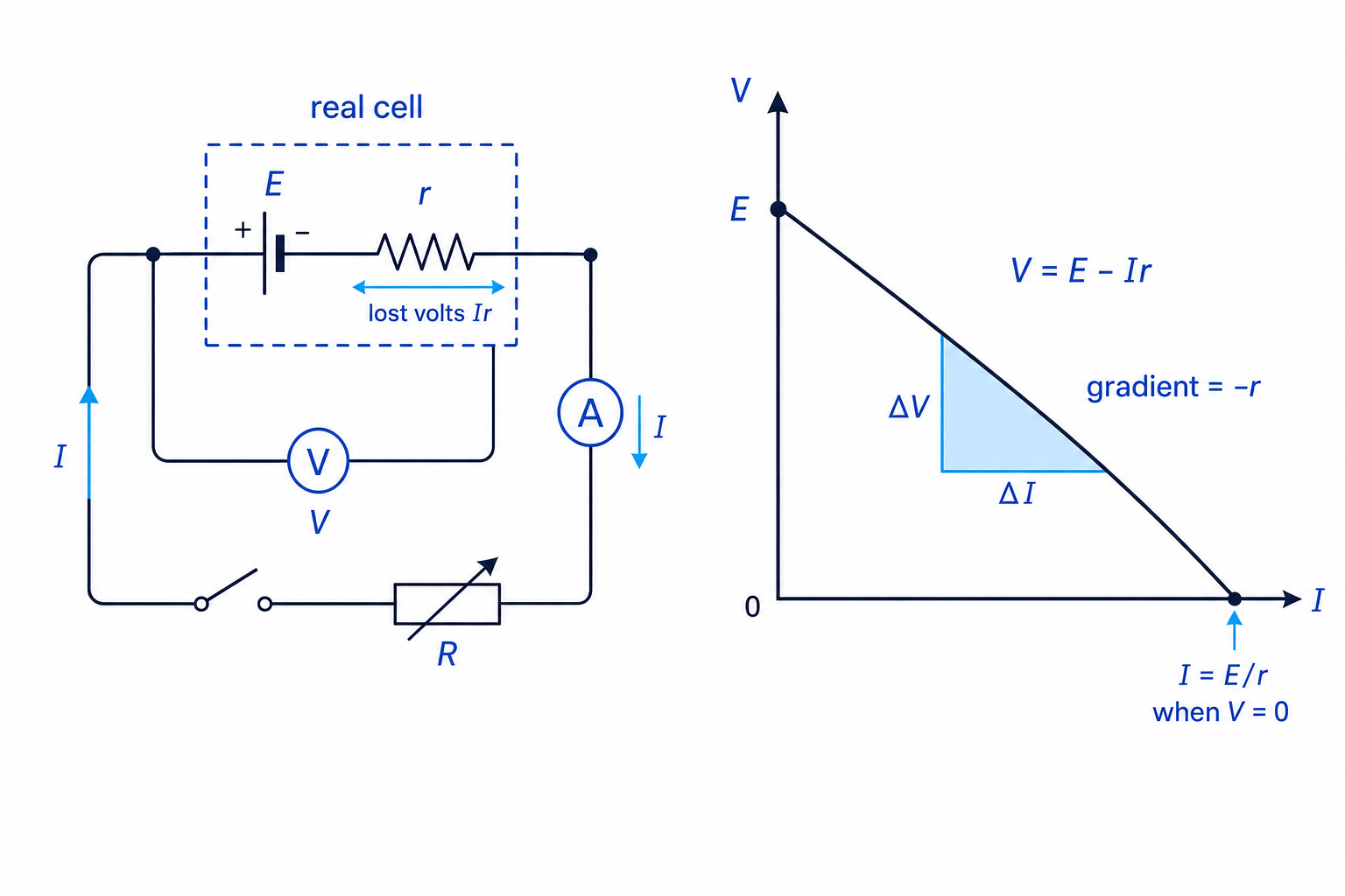
When current flows, energy is transferred inside the cell, usually heating it slightly. That internal energy transfer means not all the energy supplied by the source reaches the external circuit.
A helpful model
Think of the source as giving each coulomb some energy, but then “spending” some of that energy pushing the charge through the source’s own internal resistance before the charge reaches the external circuit.
Terminal p.d. and lost volts
The terminal p.d. is the potential difference across the external terminals of the source. This is the voltage available to the external circuit.
Terminal p.d.
The terminal potential difference, VVV, is the energy transferred per unit charge to the external circuit by the source. It is measured in volts, V.
The potential difference across the internal resistance is called the lost volts.
Lost volts
The lost volts are the potential difference across the internal resistance of a source. For a discharging source, lost volts are equal to IrIrIr.
So:
lost volts=Ir\text{lost volts} = Irlost volts=IrIf no current flows, then I=0I = 0I=0, so the lost volts are zero. In that situation, the terminal p.d. is equal to the e.m.f.
Why terminal p.d. falls
As current increases, the lost volts IrIrIr increase, so the terminal p.d. VVV decreases.
The two key equations
Suppose a source of e.m.f. EEE and internal resistance rrr is connected to an external resistance RRR.
The total resistance in the circuit is:
R+rR + rR+rSo the current is found using:
E=I(R+r)E = I(R + r)E=I(R+r)This is just V=IRV = IRV=IR applied to the whole circuit, including the internal resistance.
The terminal p.d. across the external load is:
V=IRV = IRV=IRThe lost volts are:
IrIrIrTherefore:
E=V+IrE = V + IrE=V+IrYou can also rearrange this into graph form:
V=E−IrV = E - IrV=E−IrEnergy per charge split
For a discharging source, the e.m.f. is split between the external circuit and the internal resistance: E=V+IrE = V + IrE=V+Ir.
Calculating current, terminal p.d. and lost volts
A cell has e.m.f. 1.50 V and internal resistance 0.40 Ω. It is connected to a 4.7 Ω resistor. Calculate the current, the terminal p.d., and the lost volts.
-
The external resistance and internal resistance are in series, so the total resistance is:
R+r=4.7 Ω+0.40 Ω=5.10 ΩR + r = 4.7\ \Omega + 0.40\ \Omega = 5.10\ \OmegaR+r=4.7 Ω+0.40 Ω=5.10 Ω -
Use E=I(R+r)E = I(R + r)E=I(R+r) to find the current:
I=ER+r=1.50 V5.10 Ω=0.294 AI = \frac{E}{R + r} = \frac{1.50\ \text{V}}{5.10\ \Omega} = 0.294\ \text{A}I=R+rE=5.10 Ω1.50 V=0.294 A -
The terminal p.d. is the p.d. across the external resistor:
V=IR=0.294 A×4.7 Ω=1.38 VV = IR = 0.294\ \text{A} \times 4.7\ \Omega = 1.38\ \text{V}V=IR=0.294 A×4.7 Ω=1.38 V -
The lost volts are across the internal resistance:
Ir=0.294 A×0.40 Ω=0.118 VIr = 0.294\ \text{A} \times 0.40\ \Omega = 0.118\ \text{V}Ir=0.294 A×0.40 Ω=0.118 V -
Check the energy-per-charge split:
V+Ir=1.38 V+0.118 V≈1.50 VV + Ir = 1.38\ \text{V} + 0.118\ \text{V} \approx 1.50\ \text{V}V+Ir=1.38 V+0.118 V≈1.50 VSo the answers are I=0.294 AI = 0.294\ \text{A}I=0.294 A, V=1.38 VV = 1.38\ \text{V}V=1.38 V and lost volts = 0.118 V.
Using the external resistance only
Do not use I=E/RI = E/RI=E/R for a real cell unless internal resistance is negligible. The current is set by the total resistance, so use I=E/(R+r)I = E/(R + r)I=E/(R+r).
The VVV against III graph
From:
E=V+IrE = V + IrE=V+Irrearrange to:
V=E−IrV = E - IrV=E−IrThis has the same structure as the straight-line equation y=c+mxy = c + mxy=c+mx:
- vertical axis: terminal p.d. VVV
- horizontal axis: current III
- intercept: e.m.f. EEE
- gradient: −r-r−r
So on a graph of terminal p.d. against current:
gradient=−r\text{gradient} = -rgradient=−rand therefore:
r=−gradientr = -\text{gradient}r=−gradientThe gradient has units of volts per ampere, V A⁻¹, which is equivalent to ohms, Ω.
Graph shortcut
For a VVV against III graph, the y-intercept gives EEE and the negative gradient gives rrr. If the line slopes down steeply, the source has a larger internal resistance.
Finding internal resistance from a graph
A student plots terminal p.d. VVV against current III for a cell. The best-fit line has a vertical intercept of 1.58 V. Two points on the line are: 0.20 A, 1.46 V and 0.80 A, 1.22 V. Find the e.m.f. and internal resistance.
-
The e.m.f. is the vertical intercept of the VVV against III graph:
E=1.58 VE = 1.58\ \text{V}E=1.58 V -
Calculate the gradient using the two points on the best-fit line:
gradient=1.22 V−1.46 V0.80 A−0.20 A\text{gradient} = \frac{1.22\ \text{V} - 1.46\ \text{V}}{0.80\ \text{A} - 0.20\ \text{A}}gradient=0.80 A−0.20 A1.22 V−1.46 V -
Evaluate the gradient:
gradient=−0.24 V0.60 A=−0.40 V A−1\text{gradient} = \frac{-0.24\ \text{V}}{0.60\ \text{A}} = -0.40\ \text{V A}^{-1}gradient=0.60 A−0.24 V=−0.40 V A−1 -
Since the gradient is −r-r−r:
r=0.40 Ωr = 0.40\ \Omegar=0.40 ΩThe e.m.f. is 1.58 V and the internal resistance is 0.40 Ω.
Determining internal resistance experimentally
To investigate the internal resistance of a chemical cell or other source of e.m.f., you can measure how terminal p.d. changes as current changes.
Apparatus and circuit
Use:
- the cell or power supply being tested
- an ammeter in series to measure current
- a voltmeter in parallel across the source terminals to measure terminal p.d.
- a variable resistor to change the current
- a switch to reduce unnecessary heating
The variable resistor changes the load resistance RRR. Each setting gives a different current III and terminal p.d. VVV.
Procedure
- Set up the circuit with the ammeter in series and voltmeter across the source terminals.
- Close the switch briefly and record III and VVV.
- Change the variable resistor to obtain a new current.
- Repeat for a range of current values.
- Plot a graph of VVV on the y-axis against III on the x-axis.
- Draw a line of best fit.
- Find EEE from the y-intercept and rrr from the negative gradient.
Avoid heating the cell
High currents can heat the cell and change its internal resistance during the experiment. Use the switch only while taking readings and avoid very low external resistance.
Improving the experiment
Good practical technique matters because rrr is found from a gradient, so scatter in the graph affects the answer.
Use:
- several readings over a sensible current range
- repeated readings where possible
- a line of best fit, not point-to-point joining
- large graph scales so the gradient can be found accurately
- best-fit and worst-fit lines if estimating uncertainty in rrr
Measuring the wrong voltage
The voltmeter must be connected across the source terminals, not just across the external resistor in a different part of the circuit. In this simple series circuit those are usually the same two nodes, but the exam diagram may require careful tracing.
Determining e.m.f. and internal resistance experimentally
A student obtains a straight-line VVV against III graph. The line of best fit crosses the y-axis at 6.10 V. Its gradient is −1.35 V A−1-1.35\ \text{V A}^{-1}−1.35 V A−1. State the e.m.f. and internal resistance of the source.
-
Use the y-intercept of the VVV against III graph to identify the e.m.f.:
E=6.10 VE = 6.10\ \text{V}E=6.10 V -
Use the relationship V=E−IrV = E - IrV=E−Ir, so the gradient is equal to −r-r−r:
−r=−1.35 V A−1-r = -1.35\ \text{V A}^{-1}−r=−1.35 V A−1 -
Convert the magnitude of the gradient into internal resistance:
r=1.35 Ωr = 1.35\ \Omegar=1.35 ΩSo the source has e.m.f. 6.10 V and internal resistance 1.35 Ω.
Interpreting the physics
Internal resistance is not just a mathematical trick. It explains real observations:
- A battery’s terminal p.d. falls when it supplies a large current.
- A battery can become warm when delivering current.
- Old or partly discharged cells often have larger internal resistance.
- Devices needing high current may fail even if the open-circuit voltage looks reasonable.
Quick sanity check
If current increases, lost volts IrIrIr should increase, so terminal p.d. VVV should decrease. If your calculation gives the opposite for a discharging cell, check your signs.
In the exam
- Decide whether you are dealing with the whole circuit or just the external circuit: use E=I(R+r)E = I(R + r)E=I(R+r) for the whole circuit and V=IRV = IRV=IR for the load.
- For terminal p.d. questions, start from E=V+IrE = V + IrE=V+Ir or V=E−IrV = E - IrV=E−Ir and keep the sign of the gradient in mind.
- For practical graph questions, quote EEE from the y-intercept and rrr from the magnitude of the negative gradient, with units of ohms, Ω.
Check yourself
- Why is the terminal p.d. of a cell less than its e.m.f. when current flows?
- On a VVV against III graph, what do the y-intercept and gradient represent?
- Why should the switch be opened between readings when measuring internal resistance?

