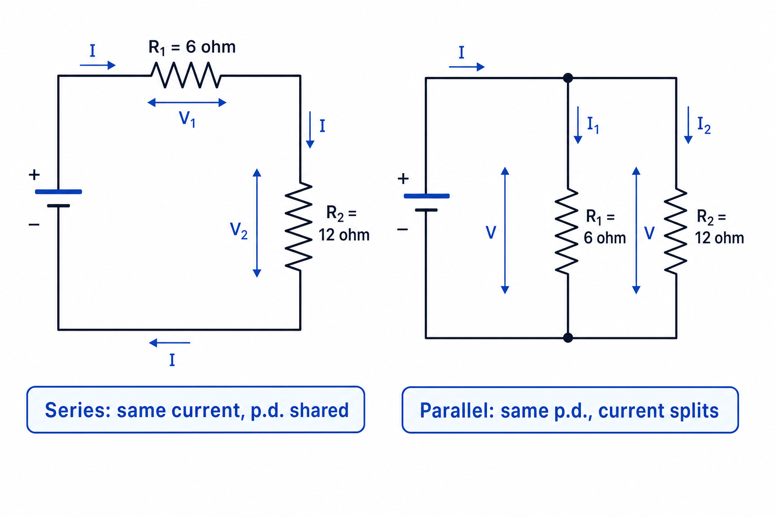
What you'll learn
- How Kirchhoff’s first law and second law come from conservation of charge and energy.
- How to calculate total resistance for resistors in series and in parallel.
- How to analyse mixed circuits using V=IRV = IRV=IR and Kirchhoff’s laws.
- How to handle circuits with more than one source of e.m.f.
The starting point: charge, current, p.d. and e.m.f.
Before series and parallel circuits feel natural, you need the core circuit quantities.
Electric current is the rate of flow of charge, measured in amperes (A). The symbol for current is III.
Potential difference, often shortened to p.d., is the energy transferred from electrical energy to other forms per unit charge as charge passes through a component. It is measured in volts (V).
Electromotive force, written as e.m.f. and usually given the symbol ε\varepsilonε, is the energy transferred to electrical energy per unit charge by a source such as a cell or power supply. It is also measured in volts.
The volt
A potential difference or e.m.f. of one volt means one joule of energy is transferred per coulomb of charge:
1 V=1 J C−11\,\text{V}=1\,\text{J}\,\text{C}^{-1}1V=1JC−1For a fixed resistor obeying Ohm’s law:
V=IRV = IRV=IRwhere VVV is potential difference in volts (V), III is current in amperes (A), and RRR is resistance in ohms (Ω\OmegaΩ).
Kirchhoff’s first law: current at a junction
A junction is a point in a circuit where a wire splits into two or more paths, or where paths rejoin.
Kirchhoff’s first law says:
total current into a junction=total current out of the junction\text{total current into a junction}=\text{total current out of the junction}total current into a junction=total current out of the junctionThis is conservation of charge. Charge cannot disappear or pile up at an ordinary junction in a steady circuit.
Kirchhoff’s first law
At a junction, currents add. If one current splits into branches, the branch currents must add up to the original current.
Finding a missing branch current
A current of 2.40 A enters a junction. It splits into three branches. Two branch currents are 0.60 A and 1.10 A. Find the third branch current.
-
Apply Kirchhoff’s first law to the junction:
I=I1+I2+I3I = I_1 + I_2 + I_3I=I1+I2+I3 -
Substitute the known currents:
2.40 A=0.60 A+1.10 A+I32.40\,\text{A}=0.60\,\text{A}+1.10\,\text{A}+I_32.40A=0.60A+1.10A+I3 -
Rearrange and calculate:
I3=2.40 A−1.70 A=0.70 AI_3=2.40\,\text{A}-1.70\,\text{A}=0.70\,\text{A}I3=2.40A−1.70A=0.70A
Kirchhoff’s second law: energy around a loop
A loop is any closed path around a circuit.
Kirchhoff’s second law says that around any closed loop:
sum of e.m.f.s=sum of potential differences\text{sum of e.m.f.s}=\text{sum of potential differences}sum of e.m.f.s=sum of potential differencesEquivalently, the algebraic sum of all potential changes around a complete loop is zero.
This is conservation of energy. Each coulomb of charge gains energy from sources, then loses the same amount of energy in components as it travels around a complete loop.
Kirchhoff’s second law
For a complete loop, energy gained per coulomb from sources equals energy transferred per coulomb in components.
Finding an unknown potential difference
A 12.0 V supply is connected in series with three components. The p.d.s across two components are 3.5 V and 4.2 V. Find the p.d. across the third component.
-
Use Kirchhoff’s second law for the loop:
ε=V1+V2+V3\varepsilon = V_1 + V_2 + V_3ε=V1+V2+V3 -
Substitute the known values:
12.0 V=3.5 V+4.2 V+V312.0\,\text{V}=3.5\,\text{V}+4.2\,\text{V}+V_312.0V=3.5V+4.2V+V3 -
Solve for the unknown p.d.:
V3=12.0 V−7.7 V=4.3 VV_3=12.0\,\text{V}-7.7\,\text{V}=4.3\,\text{V}V3=12.0V−7.7V=4.3V
Series circuits
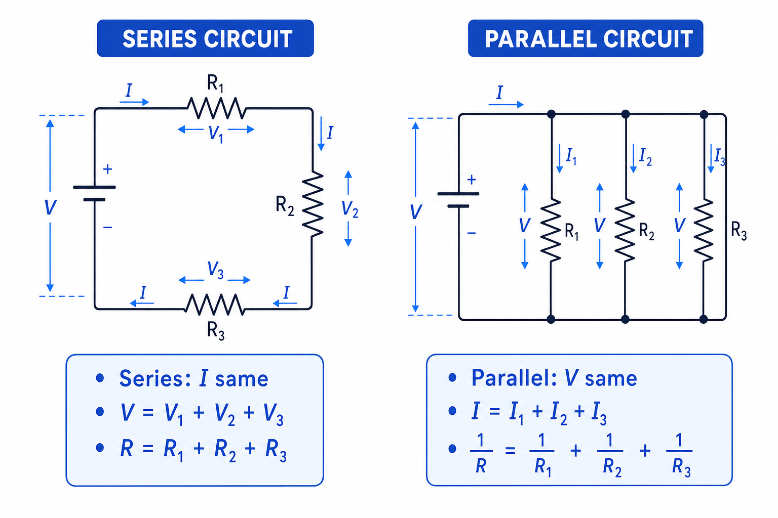
Components are in series when they are connected one after another in a single path, with no junction between them.
In a series circuit:
- the current is the same through every component
- the supply p.d. is shared between the components
- the total resistance is the sum of the individual resistances
For resistors in series:
R=R1+R2+…R = R_1 + R_2 + \ldotsR=R1+R2+…The diagram below compares the key rules for series and parallel resistor circuits.
Total resistance and current in series
A 9.0 V battery is connected to a 6.0 Ω\OmegaΩ resistor and a 12.0 Ω\OmegaΩ resistor in series. Find the total resistance and the current.
-
Add the resistances because the resistors are in series:
R=R1+R2=6.0 Ω+12.0 Ω=18.0 ΩR = R_1 + R_2 = 6.0\,\Omega + 12.0\,\Omega = 18.0\,\OmegaR=R1+R2=6.0Ω+12.0Ω=18.0Ω -
Use V=IRV = IRV=IR, rearranged to I=VRI = \frac{V}{R}I=RV:
I=9.0 V18.0 Ω=0.50 AI=\frac{9.0\,\text{V}}{18.0\,\Omega}=0.50\,\text{A}I=18.0Ω9.0V=0.50A -
Check the energy sharing by finding the p.d.s:
V1=IR1=0.50 A×6.0 Ω=3.0 VV_1=IR_1=0.50\,\text{A}\times 6.0\,\Omega=3.0\,\text{V}V1=IR1=0.50A×6.0Ω=3.0V V2=IR2=0.50 A×12.0 Ω=6.0 VV_2=IR_2=0.50\,\text{A}\times 12.0\,\Omega=6.0\,\text{V}V2=IR2=0.50A×12.0Ω=6.0VThese add to 9.0 V, matching Kirchhoff’s second law.
Using different currents in series
In a series circuit, there is only one path for charge, so the current is the same everywhere. The potential difference changes across components; the current does not.
Parallel circuits
Components are in parallel when they are connected across the same two junctions. Each branch has the same potential difference across it.
In a parallel circuit:
- the p.d. across each branch is the same
- the total current is the sum of the branch currents
- the total resistance is found using reciprocals
For resistors in parallel:
1R=1R1+1R2+…\frac{1}{R}=\frac{1}{R_1}+\frac{1}{R_2}+\ldotsR1=R11+R21+…Parallel resistance sanity check
The total resistance of resistors in parallel is always less than the smallest individual branch resistance. If your answer is larger, check your reciprocal step.
Total resistance and current in parallel
A 12.0 V supply is connected across two resistors in parallel: 6.0 Ω\OmegaΩ and 12.0 Ω\OmegaΩ. Find the total resistance and total current.
-
Use the parallel resistance equation:
1R=16.0 Ω+112.0 Ω\frac{1}{R}=\frac{1}{6.0\,\Omega}+\frac{1}{12.0\,\Omega}R1=6.0Ω1+12.0Ω1 -
Add the reciprocals:
1R=0.1667 Ω−1+0.0833 Ω−1=0.2500 Ω−1\frac{1}{R}=0.1667\,\Omega^{-1}+0.0833\,\Omega^{-1}=0.2500\,\Omega^{-1}R1=0.1667Ω−1+0.0833Ω−1=0.2500Ω−1 -
Take the reciprocal:
R=10.2500 Ω−1=4.0 ΩR=\frac{1}{0.2500\,\Omega^{-1}}=4.0\,\OmegaR=0.2500Ω−11=4.0Ω -
Use V=IRV = IRV=IR for the whole circuit:
I=VR=12.0 V4.0 Ω=3.0 AI=\frac{V}{R}=\frac{12.0\,\text{V}}{4.0\,\Omega}=3.0\,\text{A}I=RV=4.0Ω12.0V=3.0A
Adding parallel resistors directly
Do not use R=R1+R2R = R_1 + R_2R=R1+R2 for parallel branches. Adding resistances directly is only for series circuits.
Analysing circuits with both series and parallel parts
Many circuits are not purely series or purely parallel. The usual method is to simplify the circuit in stages.
A useful approach is:
- Identify any obvious series or parallel groups.
- Replace each group with its equivalent resistance.
- Find the total current from the supply using V=IRV = IRV=IR.
- Work back through the circuit to find branch currents and p.d.s.
- Check your answers using Kirchhoff’s first and second laws.
Analysing a mixed resistor circuit
A 12.0 V supply is connected to a 4.0 Ω\OmegaΩ resistor in series with a parallel pair of resistors: 6.0 Ω\OmegaΩ and 3.0 Ω\OmegaΩ. Find the total current and the current in each parallel branch.
-
First combine the parallel pair:
1R23=16.0 Ω+13.0 Ω\frac{1}{R_{23}}=\frac{1}{6.0\,\Omega}+\frac{1}{3.0\,\Omega}R231=6.0Ω1+3.0Ω1 1R23=0.1667 Ω−1+0.3333 Ω−1=0.5000 Ω−1\frac{1}{R_{23}}=0.1667\,\Omega^{-1}+0.3333\,\Omega^{-1}=0.5000\,\Omega^{-1}R231=0.1667Ω−1+0.3333Ω−1=0.5000Ω−1 R23=2.0 ΩR_{23}=2.0\,\OmegaR23=2.0Ω -
Add the series resistor:
Rtotal=4.0 Ω+2.0 Ω=6.0 ΩR_{\text{total}}=4.0\,\Omega+2.0\,\Omega=6.0\,\OmegaRtotal=4.0Ω+2.0Ω=6.0Ω -
Find the total current from the supply:
I=12.0 V6.0 Ω=2.0 AI=\frac{12.0\,\text{V}}{6.0\,\Omega}=2.0\,\text{A}I=6.0Ω12.0V=2.0A -
Find the p.d. across the 4.0 Ω\OmegaΩ series resistor:
V=IR=2.0 A×4.0 Ω=8.0 VV=IR=2.0\,\text{A}\times 4.0\,\Omega=8.0\,\text{V}V=IR=2.0A×4.0Ω=8.0VSo the p.d. across the parallel section is:
12.0 V−8.0 V=4.0 V12.0\,\text{V}-8.0\,\text{V}=4.0\,\text{V}12.0V−8.0V=4.0V -
Use the same 4.0 V across each parallel branch:
I6.0=4.0 V6.0 Ω=0.67 AI_{6.0}=\frac{4.0\,\text{V}}{6.0\,\Omega}=0.67\,\text{A}I6.0=6.0Ω4.0V=0.67A I3.0=4.0 V3.0 Ω=1.3 AI_{3.0}=\frac{4.0\,\text{V}}{3.0\,\Omega}=1.3\,\text{A}I3.0=3.0Ω4.0V=1.3AThe branch currents add to about 2.0 A, which agrees with Kirchhoff’s first law.
Circuits with more than one source of e.m.f.
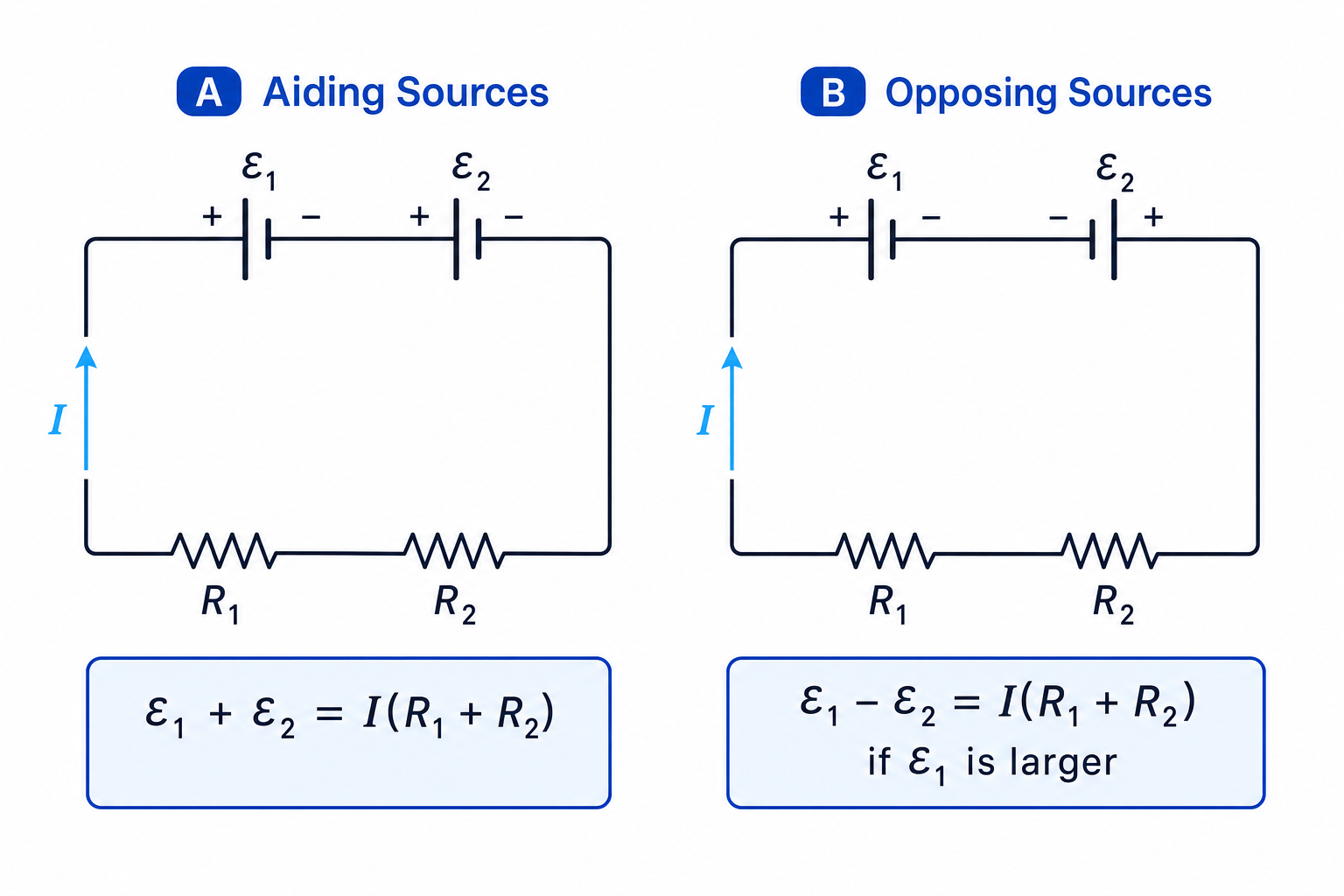
If a circuit contains more than one source, Kirchhoff’s second law still applies. The important idea is whether the sources are aiding or opposing each other.
- If sources are connected so that they drive current in the same direction, their e.m.f.s add.
- If sources are connected so that they drive current in opposite directions, their e.m.f.s subtract.
- The direction of the current is set by the larger net e.m.f.
Ideal sources unless told otherwise
At this stage, treat cells and power supplies as ideal sources of e.m.f. unless the question gives internal resistance or extra information about terminal p.d.
Calculating current with opposing sources
A 12.0 V source and a 5.0 V source are connected in opposition in a single loop with two series resistors of 4.0 Ω\OmegaΩ and 3.0 Ω\OmegaΩ. Find the current.
-
Since the sources oppose, subtract their e.m.f.s:
εnet=12.0 V−5.0 V=7.0 V\varepsilon_{\text{net}}=12.0\,\text{V}-5.0\,\text{V}=7.0\,\text{V}εnet=12.0V−5.0V=7.0V -
Add the series resistances:
Rtotal=4.0 Ω+3.0 Ω=7.0 ΩR_{\text{total}}=4.0\,\Omega+3.0\,\Omega=7.0\,\OmegaRtotal=4.0Ω+3.0Ω=7.0Ω -
Apply Kirchhoff’s second law with V=IRV = IRV=IR for the resistors:
εnet=IRtotal\varepsilon_{\text{net}}=IR_{\text{total}}εnet=IRtotal I=7.0 V7.0 Ω=1.0 AI=\frac{7.0\,\text{V}}{7.0\,\Omega}=1.0\,\text{A}I=7.0Ω7.0V=1.0A -
The current is driven in the direction of the 12.0 V source, because it has the larger e.m.f.
In the exam
- Mark series sections and parallel branches before calculating; do not rush straight into equations.
- Use Kirchhoff’s first law at junctions and Kirchhoff’s second law around loops as checks on your answer.
- For parallel resistors, calculate the reciprocal carefully and check that the total resistance is smaller than the smallest branch resistance.
Check yourself
- In a series circuit, which quantity is the same through every component?
- Why is the total resistance of two resistors in parallel less than either individual resistance?
- How would you decide whether two sources of e.m.f. should be added or subtracted?