What you'll learn
- Why multiplexing is essential for modern data communications.
- The basic principles of Time-Division Multiplexing (TDM).
- How a multiplexer and demultiplexer work together to combine and separate data streams.
- The vital role of synchronisation in keeping data channels distinct.
The problem with one wire per signal
Imagine laying a transatlantic optical fibre cable. It costs hundreds of millions of pounds and can carry a staggering amount of data (huge bandwidth). It would be incredibly wasteful if this entire cable were dedicated to carrying just one phone call or one internet stream at a time.
To make communication networks economically and practically viable, we need a way to send thousands of individual signals down a single transmission path simultaneously. The process of combining multiple signals into one is called multiplexing.
There are a few ways to do this (like sending different signals at different frequencies or colours of light), but for digital signals, the most common and logical method is Time-Division Multiplexing (TDM).
Time-division multiplexing (TDM)
A method of transmitting multiple independent digital signals across a single communication channel by dividing the time into very short intervals (slots) and assigning each signal a specific, recurring time slot.
The busy toll booth
Imagine three slow country roads (the input channels) converging onto a single, high-speed motorway (the transmission line). A traffic controller lets one car from Road A enter the motorway, then one from Road B, then one from Road C, and then loops back to Road A. As long as the motorway traffic moves fast enough, all the cars from all three slow roads can share the single motorway without colliding.
How TDM works: The MUX and DEMUX
To achieve TDM, you need a specialized electronic device at each end of the transmission line.
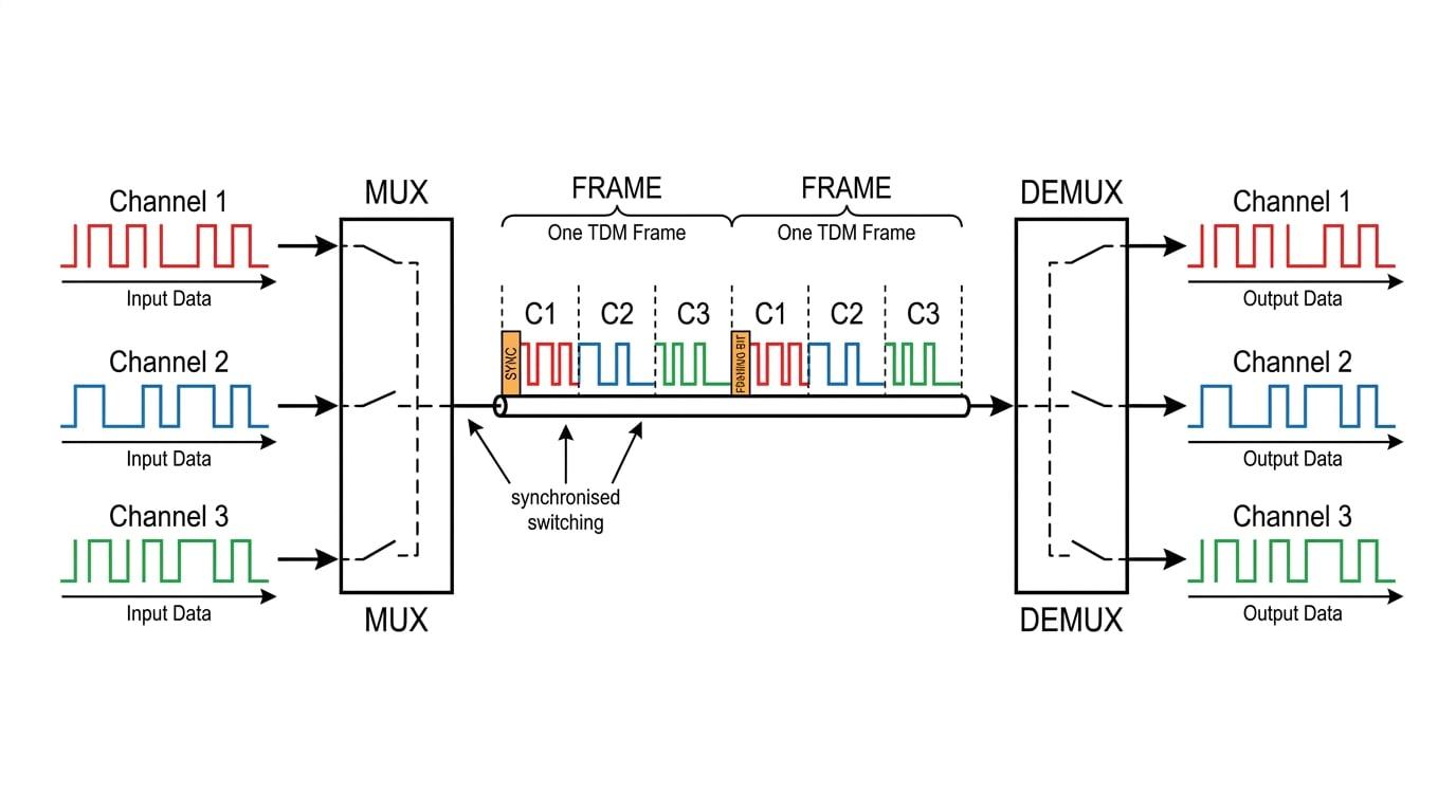
At the sending end, we use a Multiplexer (MUX). You can think of a multiplexer as an incredibly fast rotary switch. It connects to the first input channel, samples a tiny chunk of data (perhaps just a single bit or a whole byte), sends it down the main transmission line, and then instantly clicks over to the next input channel.
It cycles through all the input channels in a strict "round-robin" sequence. One complete cycle of sampling all the input channels is called a frame.
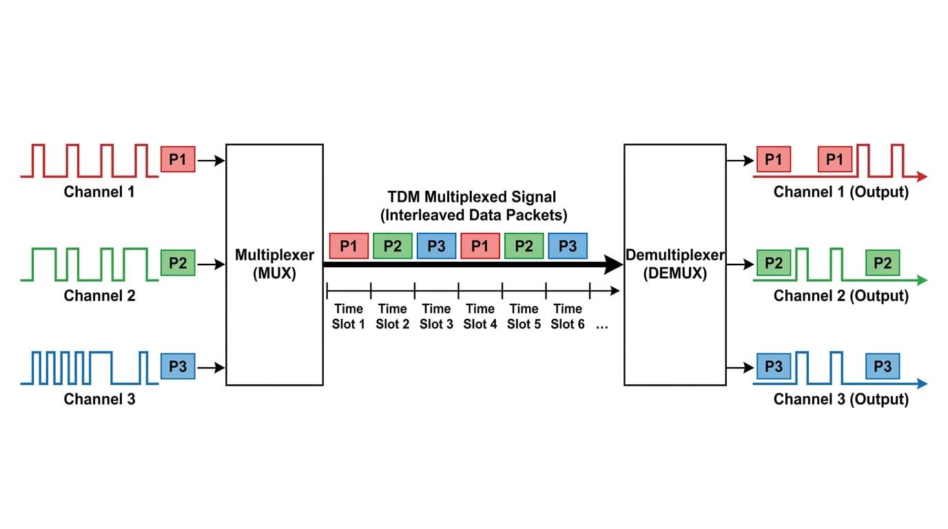
At the receiving end, we use a Demultiplexer (DEMUX). The DEMUX is the exact opposite of the MUX. It acts as another rotary switch that routes the incoming chunks of data back out to separate output channels.
The importance of synchronisation
For TDM to work, the MUX and the DEMUX must be perfectly synchronised. If the DEMUX switch falls behind or gets out of phase with the MUX switch, the data from Channel 1 will accidentally be routed into the output for Channel 2, resulting in completely scrambled data (a dropped call or a corrupted file).
To ensure the MUX and DEMUX stay locked in time together, extra synchronisation bits (often called "framing bits") are regularly inserted into the data stream. The DEMUX looks for these specific patterns to confirm it is switching at precisely the right millisecond.
Bandwidth and Bit Rate Implications
Because the main transmission line is taking turns carrying data from multiple sources, it must be capable of transmitting data much faster than any individual input channel.
If you have NNN input channels, and each channel is generating data at a bit rate RRR, the main transmission line must be able to handle a minimum bit rate of N×RN \times RN×R. In reality, because of those extra synchronisation bits we just mentioned, the required bit rate of the main line will be even higher.
Quick sanity check
If an exam question asks you to combine 5 channels that each run at 10 kbits s−110 \text{ kbits s}^{-1}10 kbits s−1, the combined stream must be at least 50 kbits s−150 \text{ kbits s}^{-1}50 kbits s−1. TDM doesn't compress data; it just packs it tightly into a faster pipe.
Calculating required transmission rates
A communications link uses time-division multiplexing to transmit 6 distinct digital audio channels over a single optical fibre. Each individual audio channel generates data at a rate of 64 kbits s−164 \text{ kbits s}^{-1}64 kbits s−1. The system also adds an overhead of 8 kbits s−18 \text{ kbits s}^{-1}8 kbits s−1 of framing data for synchronisation. Calculate the minimum total bit rate required for the main optical fibre transmission line.
- First, calculate the total data rate generated by all the input channels combined. We have 6 channels, each producing 64 kbits s−164 \text{ kbits s}^{-1}64 kbits s−1.
- Perform the multiplication to find the raw data requirement.
- Add the synchronisation overhead data to the raw channel data to find the total minimum bit rate for the main line.
Confusing TDM with FDM
Do not confuse Time-Division Multiplexing (taking turns in time) with Frequency-Division Multiplexing (FDM). In FDM, all signals are sent at the exact same time, but they are carried on different carrier frequencies (like different radio stations broadcasting simultaneously). The AQA specification for this topic specifically focuses on the principles of Time-Division multiplexing.
Summary of the TDM Process
Let's recap the step-by-step journey of data through a TDM system:
- Input: Multiple independent digital signals arrive at the multiplexer.
- Sampling: The multiplexer rapidly samples a chunk of bits from the first channel, then the second, and so on.
- Transmission: These chunks are transmitted sequentially as a single, high-speed continuous stream of data down the communication link (e.g. copper wire or optical fibre).
- Synchronisation: Special framing bits are included in the stream so the receiver knows exactly where each new cycle of data begins.
- Demultiplexing: The demultiplexer receives the high-speed stream and, staying perfectly in time with the sender, switches each chunk of data to the correct individual output channel.
In the exam
- Explain the principles clearly: If asked to explain TDM, be sure to use keywords like multiplexer, samples, time slots, sequence, and demultiplexer.
- Always mention synchronisation: It is the critical "weak point" of a TDM system. A standard 2-mark or 3-mark explanation question almost always reserves a mark for mentioning that the receiver must be synchronised with the transmitter.
- Watch your units: When calculating bit rates, pay attention to prefixes. A single channel might be in kbits s−1\text{kbits s}^{-1}kbits s−1 but the combined high-speed link might be expected in Mbits s−1\text{Mbits s}^{-1}Mbits s−1.
Check yourself
- How does a multiplexer combine multiple digital signals into one stream?
- Why is it necessary to add extra "framing bits" into a multiplexed signal?
- If 10 separate sensor signals, each producing data at 2 Mbits s−12 \text{ Mbits s}^{-1}2 Mbits s−1, are multiplexed together without any framing overhead, what is the minimum required bit rate of the transmission cable?