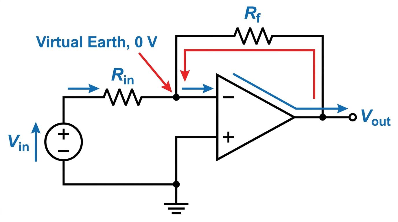
In your electronics studies so far, you have seen the "ideal" properties of an operational amplifier (op-amp). Now, it is time to put those properties to work.
What you'll learn in this topic:
- How to draw and build an inverting amplifier circuit.
- The concept of a "virtual earth" and why it exists.
- How to derive the voltage gain formula step-by-step (a common exam question!).
- How to calculate output voltages and choose appropriate resistor values.
The Inverting Amplifier Circuit
An operational amplifier on its own is usually too sensitive to be useful—its open-loop gain is so huge that even the tiniest input voltage causes the output to saturate. To control the amplifier, we use a technique called negative feedback, where we connect part of the output back to the inverting (−-−) input.
In an inverting amplifier, we apply our input signal VinV_{\text{in}}Vin to the inverting terminal via an input resistor, RinR_{\text{in}}Rin. We then connect a feedback resistor, RfR_fRf, from the output back to the inverting input. Finally, we connect the non-inverting (+++) terminal directly to ground (0 volts).
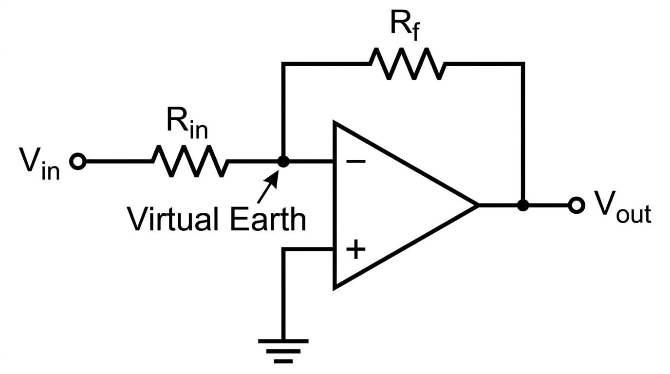
Because the signal goes into the inverting (−-−) input, the output voltage VoutV_{\text{out}}Vout will be of the opposite sign to VinV_{\text{in}}Vin. If you put in a positive voltage, you get a negative voltage out. If you put in an AC sine wave, the output will be completely out of phase (shifted by 180∘180^\circ180∘).
The Magic of the "Virtual Earth"
Before we can calculate the gain of this circuit, we need to understand a very clever concept called the virtual earth.
Let's look at the non-inverting (+++) terminal. It is connected directly to ground, so its voltage V+V_+V+ is exactly 0 volts.
Now, recall two crucial properties of an ideal op-amp:
- Infinite open-loop gain (A→∞A \to \inftyA→∞): The op-amp multiplies the potential difference between its inputs by a huge number to create the output voltage: Vout=A(V+−V−)V_{\text{out}} = A(V_+ - V_-)Vout=A(V+−V−).
- The output voltage is finite: The output is limited by the power supply (usually about ±15 V\pm 15\text{ V}±15 V).
If the output is a sensible, finite number, and the gain AAA is effectively infinite, then the potential difference between the inputs (V+−V−)(V_+ - V_-)(V+−V−) must be practically zero.
Since V+V_+V+ is exactly 0 volts, V−V_-V− is forced to also be extremely close to 0 volts.
Virtual Earth
A node in a circuit that is at a potential of 0 volts (relative to ground), but is not physically connected to the ground connection. In an inverting amplifier, the inverting input acts as a virtual earth because the op-amp's infinite open-loop gain forces the potential difference between the input terminals to be zero.
Is it actually connected to ground?
A frequent mistake is thinking the inverting input is wired to ground. It isn't! If it were wired to ground, current from the input signal would just flow harmlessly into the earth and bypass the op-amp entirely. It just behaves as if it is at 0 volts.
Deriving the Gain Formula (Virtual-Earth Analysis)
AQA loves asking you to derive the formula for the voltage gain of an inverting amplifier. You must use the "virtual earth" concept and the properties of an ideal op-amp to prove it.
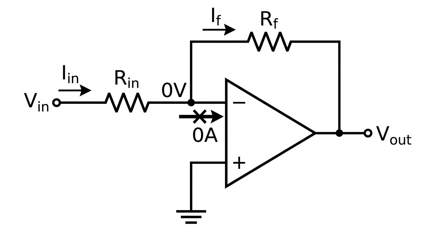
Here is the current flow in our circuit:
Let's break down the derivation step-by-step:
- Calculate the current from the input: A current IinI_{\text{in}}Iin flows from the signal source VinV_{\text{in}}Vin towards the inverting input. Because the inverting input is a virtual earth (at 0 volts), the potential difference across the input resistor is simply Vin−0V_{\text{in}} - 0Vin−0. Therefore, by Ohm's law:
- Where does the current go? An ideal op-amp has infinite input resistance. This means absolutely zero current can flow into the op-amp's inverting terminal itself.
- Calculate the current in the feedback loop: Because no current can enter the op-amp, Kirchhoff's First Law tells us that 100% of the current IinI_{\text{in}}Iin must travel up and through the feedback resistor RfR_fRf. We will call this feedback current IfI_fIf. Therefore:
- Express the feedback current in terms of voltages: The current IfI_fIf flows from the virtual earth (0 volts) to the output (VoutV_{\text{out}}Vout). The potential difference across the feedback resistor is (0−Vout)(0 - V_{\text{out}})(0−Vout). Therefore:
- Equate and rearrange: Substitute our voltage expressions into the current equality Iin=IfI_{\text{in}} = I_fIin=If:
- Multiply both sides by RfR_fRf and divide by VinV_{\text{in}}Vin to find the voltage gain (Vout/VinV_{\text{out}} / V_{\text{in}}Vout/Vin):
Voltage Gain of an Inverting Amplifier
The closed-loop voltage gain, often written as GGG or AvA_vAv, is given by:
VoutVin=−RfRin \frac{V_{\text{out}}}{V_{\text{in}}} = -\frac{R_f}{R_{\text{in}}} VinVout=−RinRf- The minus sign proves that the signal is inverted.
- The gain depends entirely on the ratio of the external resistors, not on the op-amp itself! This makes the circuit incredibly stable and predictable.
Calculations in Practice
When tackling calculations, you simply use the formula. However, always remember to check if your calculated output voltage exceeds the op-amp's power supply rails. If it does, the amplifier will saturate (clip the signal at the maximum supply voltage).
Calculating output voltage
An inverting amplifier is built using an input resistor of 10 kΩ10 \text{ k}\Omega10 kΩ and a feedback resistor of 47 kΩ47 \text{ k}\Omega47 kΩ. The op-amp is powered by a ±15 V\pm 15 \text{ V}±15 V supply. Calculate the output voltage when the input voltage is 1.2 V1.2 \text{ V}1.2 V.
- Identify the given values: Rin=10 kΩR_{\text{in}} = 10 \text{ k}\OmegaRin=10 kΩ, Rf=47 kΩR_f = 47 \text{ k}\OmegaRf=47 kΩ, Vin=1.2 VV_{\text{in}} = 1.2 \text{ V}Vin=1.2 V.
- State the gain formula:
- Calculate the voltage gain:
- Calculate the output voltage:
- Check for saturation: The magnitude of −5.64 V-5.64 \text{ V}−5.64 V is comfortably less than the 15 V15 \text{ V}15 V supply, so the amplifier will not saturate. The final answer is −5.6 V-5.6 \text{ V}−5.6 V (to 2 sig figs).
Handling prefixes
Because the gain formula is a ratio, you do not always need to convert kΩ\text{k}\OmegakΩ to Ω\OmegaΩ as long as both resistors are in the same unit. For instance, 47 kΩ/10 kΩ47\text{ k}\Omega / 10\text{ k}\Omega47 kΩ/10 kΩ gives the exact same result as 47000 Ω/10000 Ω47000\text{ }\Omega / 10000\text{ }\Omega47000 Ω/10000 Ω. Just be careful not to mix kΩ\text{k}\OmegakΩ and MΩ\text{M}\OmegaMΩ!
Sometimes you are asked to work backwards to choose a resistor to achieve a specific gain.
Designing a specific gain
An engineer needs an inverting amplifier with a voltage gain of −12-12−12. They have a 120 kΩ120 \text{ k}\Omega120 kΩ resistor available to use as the feedback resistor. What value should they choose for the input resistor?
- State the given values: Gain =−12= -12=−12, Rf=120 kΩR_f = 120 \text{ k}\OmegaRf=120 kΩ.
- Write out the gain formula:
- Substitute the known values:
- Rearrange to solve for RinR_{\text{in}}Rin:
In the exam
- Learn the derivation off by heart: This is a very common 3 or 4-mark question. You must explicitly state why current does not enter the op-amp ("infinite input resistance") and why the inverting input is at 0V ("infinite open-loop gain and grounded non-inverting input").
- Watch the negative sign: If the question asks for the "voltage gain", include the minus sign. If it asks for the "magnitude of the voltage gain", leave the minus sign off. If it asks for VoutV_{\text{out}}Vout, make sure it has the opposite sign to VinV_{\text{in}}Vin.
- Always do a sanity check for saturation: If your calculation suggests Vout=25 VV_{\text{out}} = 25\text{ V}Vout=25 V but the question states the supply rails are ±12 V\pm 12\text{ V}±12 V, your final answer for the output voltage must be +12 V+12\text{ V}+12 V or −12 V-12\text{ V}−12 V (saturated), not 25 V25\text{ V}25 V.
Check yourself
- Can you draw the schematic for an inverting amplifier from memory, making sure the input signal goes to the correct terminal?
- What two ideal properties of an op-amp are used to prove that Iin=IfI_{\text{in}} = I_fIin=If and that the inverting input is a virtual earth?
- If RfR_fRf is 100 kΩ100\text{ k}\Omega100 kΩ and RinR_{\text{in}}Rin is 20 kΩ20\text{ k}\Omega20 kΩ, and the input is −2 V-2\text{ V}−2 V, what will the output voltage be?