The ideal operational amplifier (A-level only)
What you'll learn:
- What an operational amplifier (op-amp) is and how it connects to a circuit.
- The two defining characteristics of an ideal op-amp.
- How to use the open-loop transfer function to calculate output voltage.
- How an op-amp functions as a simple comparator to make decisions in circuits.
The Op-Amp as a System Building Block
Inside a real operational amplifier, there are dozens of tiny transistors, resistors, and capacitors working together. Fortunately, in A-level Physics, we do not need to understand its internal circuitry.
Instead, we treat the op-amp as a system building block. This means we view it as a "black box" that performs a specific, reliable function. By combining op-amps with standard components like resistors and capacitors, we can easily build complex analogue signal processing circuits (like amplifiers, filters, and oscillators).
Signal and Power Connections
An op-amp is represented in circuit diagrams as a triangle pointing in the direction of signal flow (from left to right).
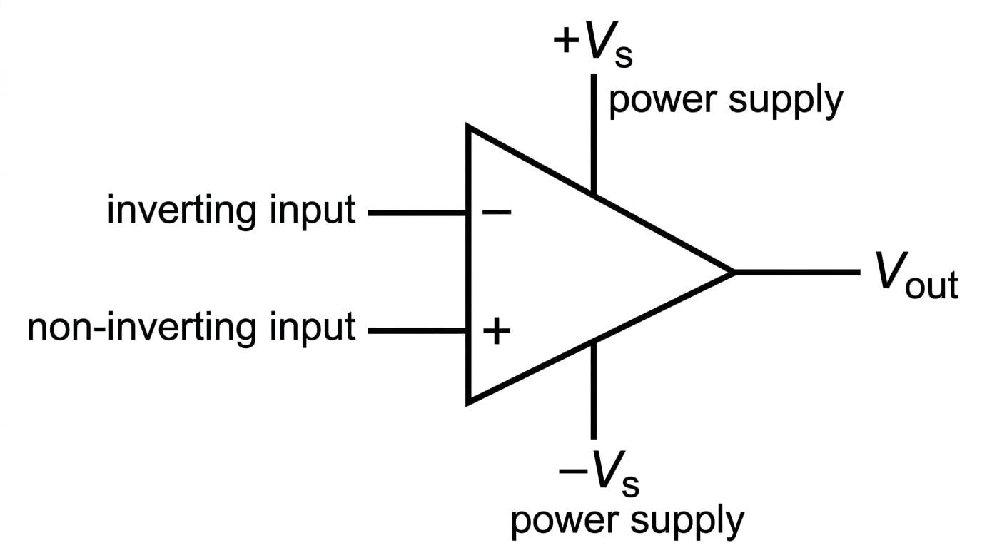
There are five main connections you need to know:
- Inverting input (−-−): A signal applied here is amplified and inverted (flipped upside down or multiplied by a negative number).
- Non-inverting input (+++): A signal applied here is amplified but keeps its original polarity.
- Output (VoutV_{\text{out}}Vout): The single pin where the processed signal leaves the op-amp.
- Positive power supply (+Vs+V_s+Vs): Op-amps are active components; they need external power to work. This is typically connected to a positive DC voltage, like +15 V.
- Negative power supply (−Vs-V_s−Vs): This is typically connected to a negative DC voltage, like -15 V, or sometimes to 0 V (ground).
Open-loop
"Open-loop" simply means there is no feedback connection in the circuit. The output is not wired back to either of the inputs. The op-amp is simply taking the inputs, doing its job, and sending the result directly to the output.
Characteristics of an Ideal Op-Amp
Real op-amps are incredibly complex and have minor imperfections. To make designing circuits easier, we use a theoretical model called the ideal op-amp. You must memorize its two main characteristics:
1. Infinite Input Resistance
The resistance between the two input terminals is assumed to be infinite.
- Practical consequence: Absolutely zero current flows into or out of the inverting or non-inverting inputs. The op-amp "looks" at the voltage of the incoming signals without drawing any electrical current from them.
2. Infinite Open-Loop Gain
Gain is the multiplier by which an amplifier increases a signal. An ideal op-amp has an infinite open-loop gain.
- Practical consequence: Any voltage difference between the two inputs, no matter how microscopically small, will be multiplied by infinity. In a real circuit, this causes the output voltage to instantly shoot up to the maximum possible value the power supply allows.
The Golden Rules of the Ideal Op-Amp
Whenever you analyze an op-amp circuit, start by reminding yourself:
- No current flows into the inputs.
- If it is in open-loop, a tiny difference in input voltages causes a huge output voltage.
The Open-Loop Transfer Function
For a real op-amp, the open-loop gain is not quite infinite, but it is typically extremely large (often around 10510^5105). We call this open-loop gain AOLA_{\text{OL}}AOL.
The op-amp works by amplifying the difference between the voltages at its two inputs. This relationship is given by the open-loop transfer function:
Vout=AOL(V+−V−) V_{\text{out}} = A_{\text{OL}}(V_+ - V_-) Vout=AOL(V+−V−)- VoutV_{\text{out}}Vout is the output voltage.
- AOLA_{\text{OL}}AOL is the open-loop gain (no units).
- V+V_+V+ is the voltage at the non-inverting input.
- V−V_-V− is the voltage at the inverting input.
Saturation
An amplifier cannot create energy out of nowhere. The output voltage VoutV_{\text{out}}Vout can never exceed the power supply voltages (+Vs+V_s+Vs and −Vs-V_s−Vs).
If the formula calculates a VoutV_{\text{out}}Vout that is greater than +Vs+V_s+Vs, the op-amp simply outputs +Vs+V_s+Vs. We say the op-amp is saturated.
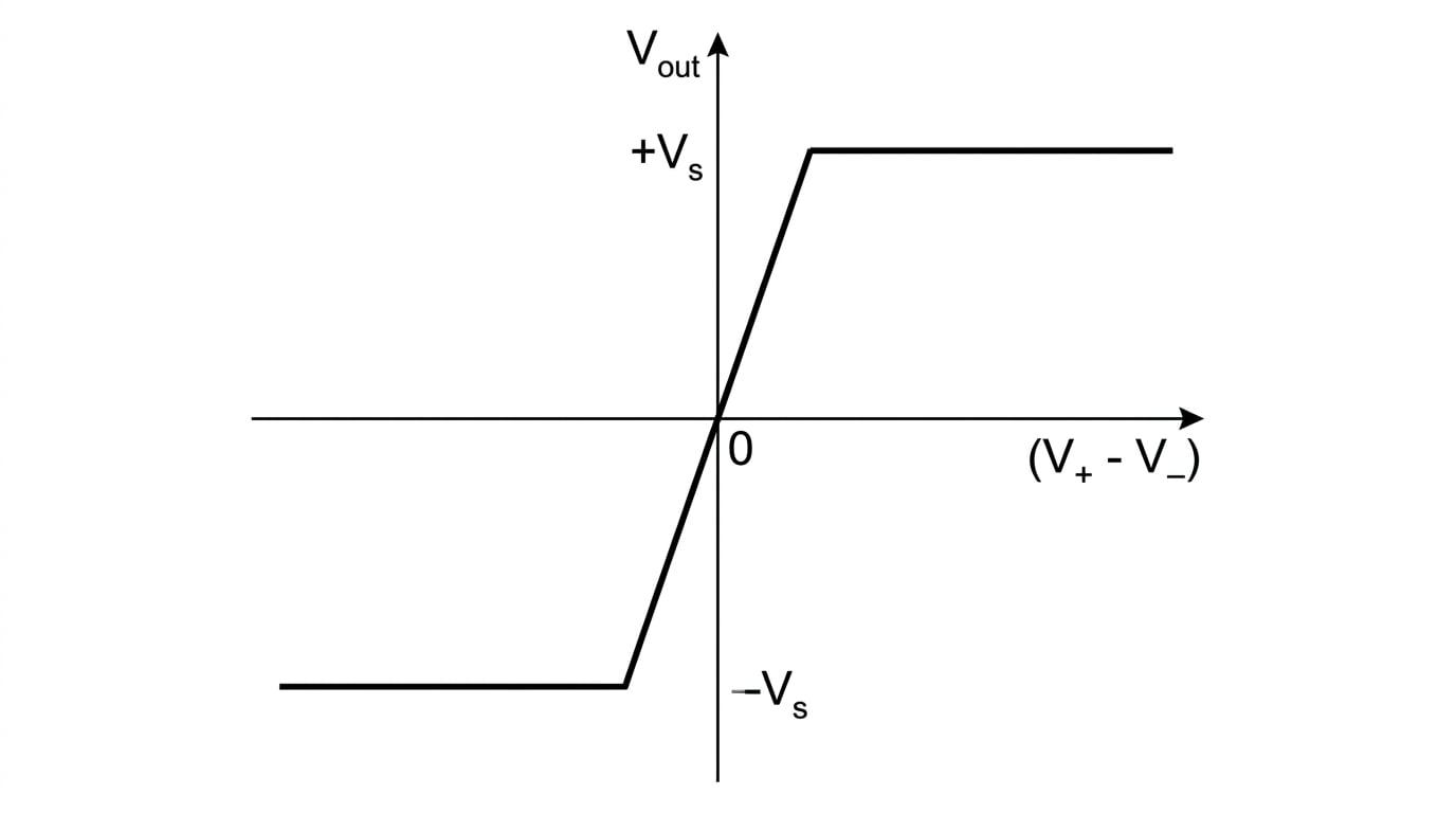
Notice how narrow the central diagonal line is. Because AOLA_{\text{OL}}AOL is so massive, even a tiny difference of a few microvolts between V+V_+V+ and V−V_-V− is enough to drive the output firmly into saturation.
Calculating Output Voltage
An operational amplifier has an open-loop gain of 2×1052 \times 10^52×105 and is powered by a ±15 V\pm 15\text{ V}±15 V supply. The voltage at the inverting input is 2.4000 V2.4000\text{ V}2.4000 V and the voltage at the non-inverting input is 2.4001 V2.4001\text{ V}2.4001 V.
Determine the output voltage.
- State the open-loop transfer function:
- Identify the known values from the question:
- Substitute the values into the equation:
- Check against the power supply limits. The supply is ±15 V\pm 15\text{ V}±15 V. Because 20 V20\text{ V}20 V is greater than 15 V15\text{ V}15 V, the op-amp will saturate.
- State the final answer: The op-amp saturates, so Vout=15 VV_{\text{out}} = 15\text{ V}Vout=15 V.
Watch your signs
Always strictly follow the order (V+−V−)(V_+ - V_-)(V+−V−). If V−V_-V− is larger than V+V_+V+, the bracket becomes negative, and the op-amp will drive towards negative saturation (−Vs-V_s−Vs).
The Op-Amp as a Comparator
Because the open-loop gain is so huge, an op-amp in an open-loop configuration acts essentially as a digital switch. It compares the two input voltages and makes a binary decision:
- If V+>V−V_+ > V_-V+>V−, the output swings instantly to +Vs+V_s+Vs (positive saturation).
- If V+<V−V_+ < V_-V+<V−, the output swings instantly to −Vs-V_s−Vs (negative saturation).
This specific application is called a comparator. Comparators are the heart of sensor circuits (like automated streetlights or thermostats). Usually, one input is connected to a fixed reference voltage, and the other is connected to a sensor (like a thermistor or LDR) in a potential divider.
A Simple Thermostat Logic
An op-amp is configured as a comparator. The inverting input (−-−) is wired to a fixed reference voltage of 5 V5\text{ V}5 V. The non-inverting input (+++) is wired to a temperature sensor. The sensor outputs 4 V4\text{ V}4 V when the room is cold, and 6 V6\text{ V}6 V when the room is hot. The power supply is ±12 V\pm 12\text{ V}±12 V.
Explain the behavior of the output voltage as the room heats up.
- Identify the fixed reference voltage:
- Analyze the "cold" state:
Since V+<V−V_+ < V_-V+<V−, the transfer function (V+−V−)(V_+ - V_-)(V+−V−) yields a negative number. 3. Determine the cold output: The op-amp saturates negatively.
Vout=−12 V V_{\text{out}} = -12\text{ V} Vout=−12 V- Analyze the "hot" state:
Since V+>V−V_+ > V_-V+>V−, the transfer function (V+−V−)(V_+ - V_-)(V+−V−) yields a positive number. 5. Determine the hot output: The op-amp saturates positively.
Vout=+12 V V_{\text{out}} = +12\text{ V} Vout=+12 V- Conclusion: As the room heats up and the sensor voltage crosses the 5 V5\text{ V}5 V threshold, the output abruptly switches from −12 V-12\text{ V}−12 V to +12 V+12\text{ V}+12 V.
In the exam
- If a question asks you to define an ideal op-amp, always list both "infinite open-loop gain" and "infinite input resistance".
- When calculating VoutV_{\text{out}}Vout using the transfer function, your final step must always be to check the power supply limits. Examiners love to award a final mark for recognizing saturation.
- Pay close attention to the labels on the inputs. Sometimes diagrams draw the inverting input on the top, and sometimes on the bottom. Don't assume the top wire is always V+V_+V+.
Check yourself
- Can you draw the circuit symbol for an op-amp and accurately label all five main connections?
- Why do we assume no current flows into the inputs of an ideal op-amp?
- If an op-amp is powered by a ±9 V\pm 9\text{ V}±9 V supply and acts as a comparator, what are the two possible output voltages it will normally settle at?