non-inverting amplifier configuration (A-level only)
Welcome to the non-inverting amplifier! In this topic, we will look at a very common way to wire up an operational amplifier (op-amp).
What you'll learn
- How to draw and recognise a non-inverting amplifier circuit.
- How to use the non-inverting voltage gain equation.
- Why this setup doesn't invert the input signal, and why its gain is always greater than or equal to 1.
The Basics: What is a Non-Inverting Amplifier?
As you already know, an operational amplifier is a component that amplifies the voltage difference between its two inputs. In most practical circuits, we use a concept called negative feedback to control this massive gain and make the op-amp stable and useful.
In an inverting amplifier, the input signal is fed into the inverting (−-−) terminal, which flips the signal upside down (a phase shift of 180°).
However, sometimes you want to make a signal bigger without flipping it upside down. For example, if you are amplifying an audio signal from a microphone, you might want the output voltage to rise exactly when the input voltage rises. This is where the non-inverting amplifier comes in.
To achieve this, we feed the input voltage directly into the non-inverting (+++) terminal.
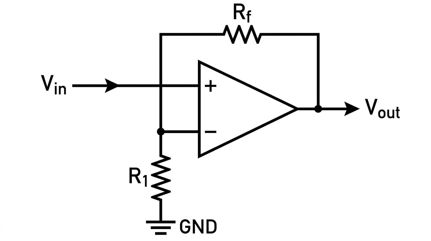
Anatomy of the Circuit
Let's look closely at how the circuit is built:
- The input voltage VinV_{\text{in}}Vin is connected directly to the non-inverting terminal (+++).
- The output voltage VoutV_{\text{out}}Vout is connected back to the inverting terminal (−-−) through a feedback resistor, RfR_fRf.
- A second resistor, R1R_1R1, connects the inverting terminal (−-−) to 0 V (ground).
Because the feedback connects back to the negative terminal, the circuit uses negative feedback. The op-amp will automatically adjust its output voltage to whatever level is needed to keep the voltage at the −-− terminal exactly equal to the voltage at the +++ terminal.
The Voltage Gain Equation
In AQA A-Level Physics, you do not need to derive the formula for the non-inverting amplifier from scratch, but you absolutely must know how to use it.
Voltage Gain
The voltage gain of an amplifier is the ratio of the output voltage to the input voltage. It has no units because it is a ratio of two voltages.
For a non-inverting amplifier, the gain is determined entirely by the two external resistors, RfR_fRf and R1R_1R1. The formula given in your specification is:
VoutVin=1+RfR1 \frac{V_{\text{out}}}{V_{\text{in}}} = 1 + \frac{R_f}{R_1} VinVout=1+R1RfWhere:
- VoutV_{\text{out}}Vout is the output voltage (in volts, V).
- VinV_{\text{in}}Vin is the input voltage (in volts, V).
- RfR_fRf is the feedback resistor (in ohms, Ω\OmegaΩ).
- R1R_1R1 is the input resistor to ground (in ohms, Ω\OmegaΩ).
A Positive Gain
Because resistance values cannot be negative, the term RfR1\frac{R_f}{R_1}R1Rf must be positive. This means that the gain (1+RfR11 + \frac{R_f}{R_1}1+R1Rf) is always positive and always greater than or equal to 1. A positive gain confirms that the output is in phase with the input (it isn't inverted!).
Mixing up the resistors
The most frequent error students make in exams is getting RfR_fRf and R1R_1R1 upside down in the fraction. Always trace the circuit diagram carefully: RfR_fRf is the resistor in the feedback loop (bridging the output to the input), and R1R_1R1 is the resistor connecting the inverting terminal to ground.
Putting the Equation to Use
Let's look at how AQA might test this in a written paper. Often, you will be given a circuit diagram with resistor values and an input voltage, and asked to find the output voltage.
Calculating the output voltage
A non-inverting amplifier is constructed with a feedback resistor of 12 kΩ12 \text{ k}\Omega12 kΩ and a resistor to ground of 3.0 kΩ3.0 \text{ k}\Omega3.0 kΩ. An input signal of 0.50 V0.50 \text{ V}0.50 V is applied. Calculate the output voltage.
- Identify the given values from the question: Rf=12 kΩR_f = 12 \text{ k}\OmegaRf=12 kΩ, R1=3.0 kΩR_1 = 3.0 \text{ k}\OmegaR1=3.0 kΩ, and Vin=0.50 VV_{\text{in}} = 0.50 \text{ V}Vin=0.50 V.
- Write down the gain equation:
- Substitute the resistor values into the right-hand side. Because both resistors are in kΩ\text{k}\OmegakΩ, the units will cancel out, so we can just use the values 12 and 3.0:
- Calculate the gain:
- Multiply the gain by the input voltage to find VoutV_{\text{out}}Vout:
Dealing with Saturation
Just like an inverting amplifier, a non-inverting amplifier cannot magically produce an infinite voltage. The output voltage is strictly limited by the power supply rails (often +15 V+15 \text{ V}+15 V and −15 V-15 \text{ V}−15 V).
Saturation limits
If your calculation gives a VoutV_{\text{out}}Vout that is larger than the power supply voltage, the op-amp will saturate. The output voltage will just stay flat at the maximum supply voltage (e.g. 15 V15 \text{ V}15 V), and the peaks of the signal will be "clipped" off. If an exam question gives you the supply voltages, always double-check that your calculated VoutV_{\text{out}}Vout doesn't exceed them!
Designing a Non-Inverting Amplifier
Sometimes, rather than finding the output voltage, the exam question will ask you to work backwards. You'll be given the desired gain and one resistor, and you'll need to calculate the size of the other resistor to make the circuit work.
Designing for a specific gain
An engineer needs a non-inverting amplifier to have a voltage gain of 8.5. They have a 15 kΩ15 \text{ k}\Omega15 kΩ resistor to use for RfR_fRf. Calculate the required resistance for R1R_1R1.
- State the required gain and the known resistor: Gain=8.5\text{Gain} = 8.5Gain=8.5, Rf=15 kΩR_f = 15 \text{ k}\OmegaRf=15 kΩ.
- Set up the gain equation:
- Subtract 1 from both sides to isolate the fraction:
- Rearrange to make R1R_1R1 the subject:
- Calculate the final value:
The Unity Gain Buffer
What happens if Rf=0 ΩR_f = 0 \text{ }\OmegaRf=0 Ω (just a plain wire) and we remove R1R_1R1 altogether? The fraction RfR1\frac{R_f}{R_1}R1Rf becomes 0, and the equation simplifies to VoutVin=1\frac{V_{\text{out}}}{V_{\text{in}}} = 1VinVout=1. The output voltage is exactly the same as the input voltage! This special case is called a voltage follower or buffer, and it's brilliant for isolating different parts of a circuit without changing the signal's size.
In the exam
- Check the terminals: Before doing any maths, look closely at where VinV_{\text{in}}Vin goes. If it goes to the +++ terminal, it's non-inverting. If it goes to the −-− terminal, it's inverting, and you need a different formula!
- Watch your prefixes: RfR_fRf and R1R_1R1 are almost always given in kΩ\text{k}\OmegakΩ or MΩ\text{M}\OmegaMΩ. As long as they are both in the same units, you don't have to convert them to ohms, because the ratio RfR1\frac{R_f}{R_1}R1Rf will be the same. But if one is in kΩ\text{k}\OmegakΩ and the other in MΩ\text{M}\OmegaMΩ, convert them both to Ω\OmegaΩ first!
- Remember the '+ 1': The most common careless math error is calculating just RfR1\frac{R_f}{R_1}R1Rf and forgetting to add 1 at the end. Write the full equation out every time to avoid this.
Check yourself
- Can you draw a non-inverting amplifier circuit from memory, correctly labelling RfR_fRf, R1R_1R1, VinV_{\text{in}}Vin, and VoutV_{\text{out}}Vout?
- If RfR_fRf and R1R_1R1 are equal in value, what is the voltage gain of the amplifier?
- Why can the voltage gain of a non-inverting amplifier never be 0.5?
- If an op-amp has ±12 V\pm 12 \text{ V}±12 V supply rails, a gain of 10, and an input of 2.0 V2.0 \text{ V}2.0 V, what will the actual output voltage be?