

What you'll learn
- How current, charge, voltage, resistance and energy are linked in circuits.
- Why series and parallel circuits are useful for different applications, including domestic lighting.
- How to calculate currents, voltages and resistances in simple series circuits.
- How current–voltage graphs are different for resistors, filament lamps and diodes.
1. Charge and current
Electric circuits transfer energy because electric charge moves around the circuit.
In solid metallic conductors, such as copper wires, the moving charges are negatively charged electrons. They drift through the metal when a voltage is applied.
Current
Electric current is the rate of flow of charge. It is measured in amperes, A. Charge is measured in coulombs, C.
The spec equation is:
charge = current × time
Q=I×t Q = I \times t Q=I×twhere QQQ is charge in C, III is current in A, and ttt is time in s.
Rearranged:
I=Qt I = \frac{Q}{t} I=tQConventional current is shown flowing from the positive terminal to the negative terminal. In metals, electrons actually move the opposite way.
2. Voltage and resistance
A voltage is sometimes called a potential difference. It tells you how much energy is transferred by each coulomb of charge.
Resistance is how much a component opposes the flow of current. It is measured in ohms, Ω.
Resistance
For a fixed voltage, increasing the resistance decreases the current. Decreasing the resistance increases the current.
The spec equation is:
voltage = current × resistance
V=I×R V = I \times R V=I×Rwhere VVV is voltage in V, III is current in A, and RRR is resistance in Ω.
Useful rearrangements are:
I=VR I = \frac{V}{R} I=RV R=VI R = \frac{V}{I} R=IV3. Series and parallel circuits
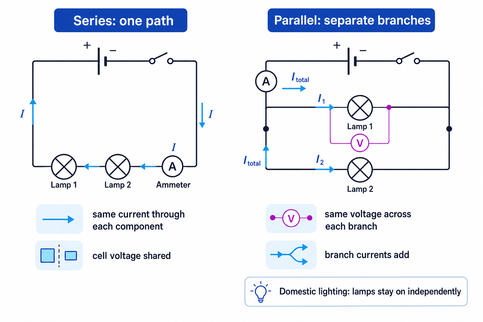
A series circuit has one path for current. A parallel circuit has two or more branches.
Series circuits
In a series circuit:
- the current is the same through every component
- the supply voltage is shared between the components
- adding more components usually increases the total resistance, so the current decreases
- the current depends on the applied voltage and on the number and nature of the components
The “nature” of a component matters because not all components have constant resistance. For example, a filament lamp heats up and its resistance changes.
Parallel circuits
In a parallel circuit:
- the voltage across each branch is the same
- the current splits at junctions and recombines later
- components can be switched on and off independently
For two components connected in parallel:
V1=V2=Vsupply V_1 = V_2 = V_\text{supply} V1=V2=VsupplyParallel circuits are more appropriate for domestic lighting because each lamp gets the full mains voltage and one lamp failing does not stop the others working.
Choosing the circuit type
Use series when every component must be in the same loop, such as a switch in series with a lamp. Use parallel when components need to work independently, such as lamps in a house.
Choosing a circuit for domestic lighting
- A house needs each lamp to receive the normal supply voltage so it can glow at the correct brightness.
- In a series circuit, the voltage would be shared and one broken lamp would open the whole circuit.
- In a parallel circuit, each lamp has the same voltage across it and each branch can work independently, so domestic lighting should be connected in parallel.
4. Calculating in a series circuit
For two resistive components in series:
Rtotal=R1+R2 R_\text{total} = R_1 + R_2 Rtotal=R1+R2The same current flows through both components, and the supply voltage is shared:
Vsupply=V1+V2 V_\text{supply} = V_1 + V_2 Vsupply=V1+V2Calculating current and voltage in series
Two resistors, 4 Ω and 8 Ω, are connected in series to a 12 V supply. Find the current and the voltage across each resistor.
- Add the resistances because the components are in series:
- Use I=VRI = \frac{V}{R}I=RV for the whole circuit:
- Use V=I×RV = I \times RV=I×R for each resistor:
- Check the voltages add to the supply:
5. Current at junctions
At a junction, current is conserved. This means the total current entering the junction equals the total current leaving it.
This happens because charge cannot disappear or pile up at a junction in a steady circuit.
For two branches:
Itotal=I1+I2 I_\text{total} = I_1 + I_2 Itotal=I1+I2Losing current at a junction
Current does not get “used up” at a junction. Energy is transferred in components, but charge flow is conserved.
6. Current–voltage characteristics
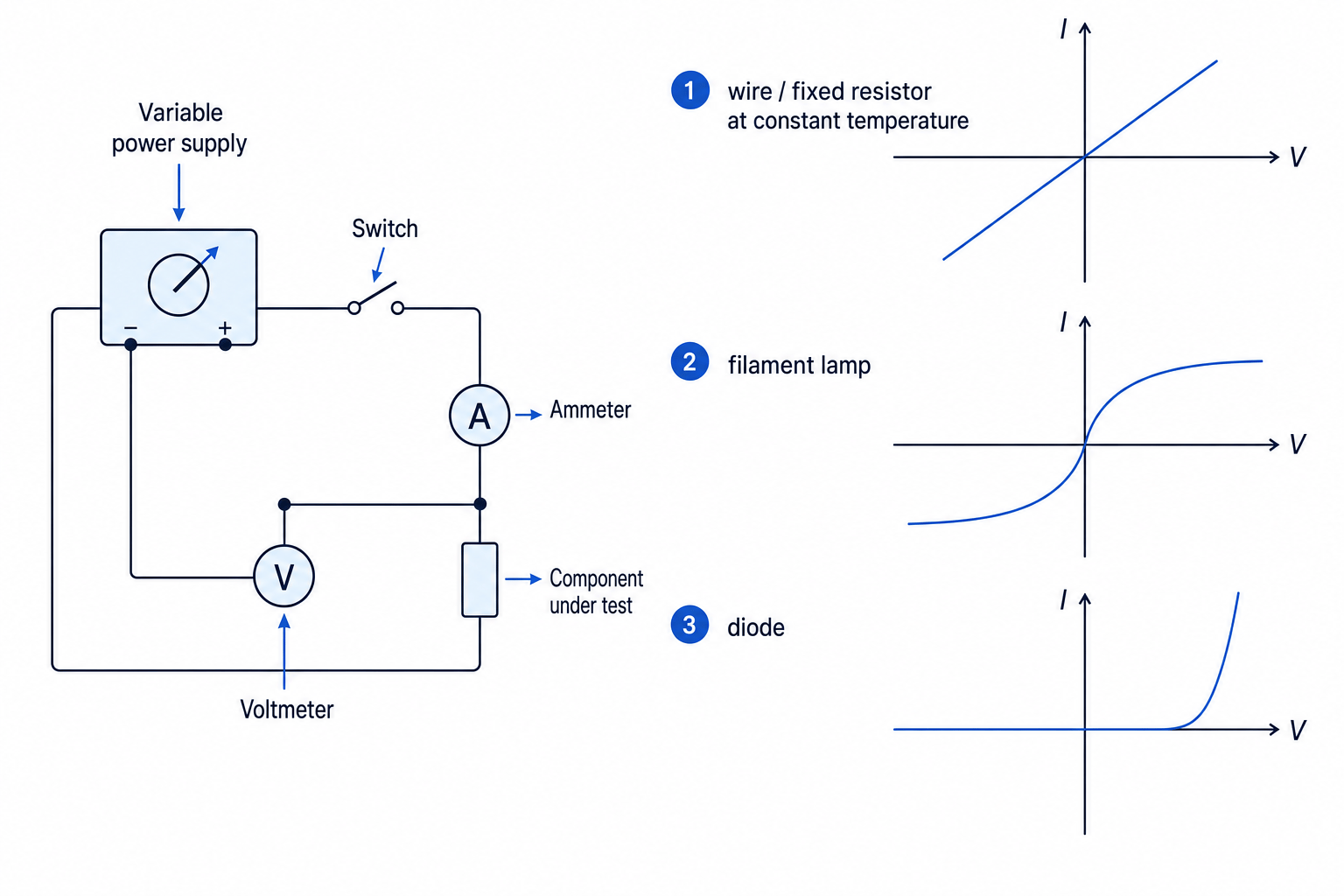
A current–voltage characteristic shows how current changes as voltage changes for a component.
Wires and fixed resistors
For a wire or fixed resistor at constant temperature, current is directly proportional to voltage. The graph is a straight line through the origin.
This means the resistance is constant.
Metal filament lamps
In a metal filament lamp, increasing current heats the filament. A hotter filament has greater resistance, so current does not rise as quickly as voltage.
The graph curves and becomes less steep at higher voltages.
Diodes and LEDs
A diode allows current to flow much more easily in one direction than the other. In reverse, the current is almost zero. In the forward direction, the current rises sharply after a certain voltage.
An LED, or light-emitting diode, emits light when current flows through it in the forward direction.
Lamps and LEDs can be used to indicate the presence of a current in a circuit, because they light up when current flows.
Meter positions
An ammeter must be connected in series with the component. A voltmeter must be connected in parallel across the component.
7. Investigating current–voltage graphs
To investigate how current varies with voltage, use:
- variable power supply
- component under test
- ammeter in series
- voltmeter in parallel
- switch
- connecting leads
Method:
- Connect the circuit with the ammeter in series and the voltmeter across the component.
- Start with a low voltage and close the switch briefly.
- Record the voltage and current.
- Increase the voltage in steps and repeat.
- Reverse the supply connections if negative voltage readings are needed.
- Plot current on the y-axis against voltage on the x-axis.
The independent variable is voltage. The dependent variable is current. Important control variables include the component used and, for a resistor or wire, the temperature.
To reduce errors, switch off between readings to reduce heating, avoid loose connections, and do not use currents large enough to damage a diode or LED.
8. LDRs and thermistors
Some components are designed so their resistance changes with conditions.
An LDR, or light-dependent resistor, has lower resistance when illumination increases.
A thermistor used at IGCSE is usually an NTC thermistor: its resistance decreases as temperature increases.
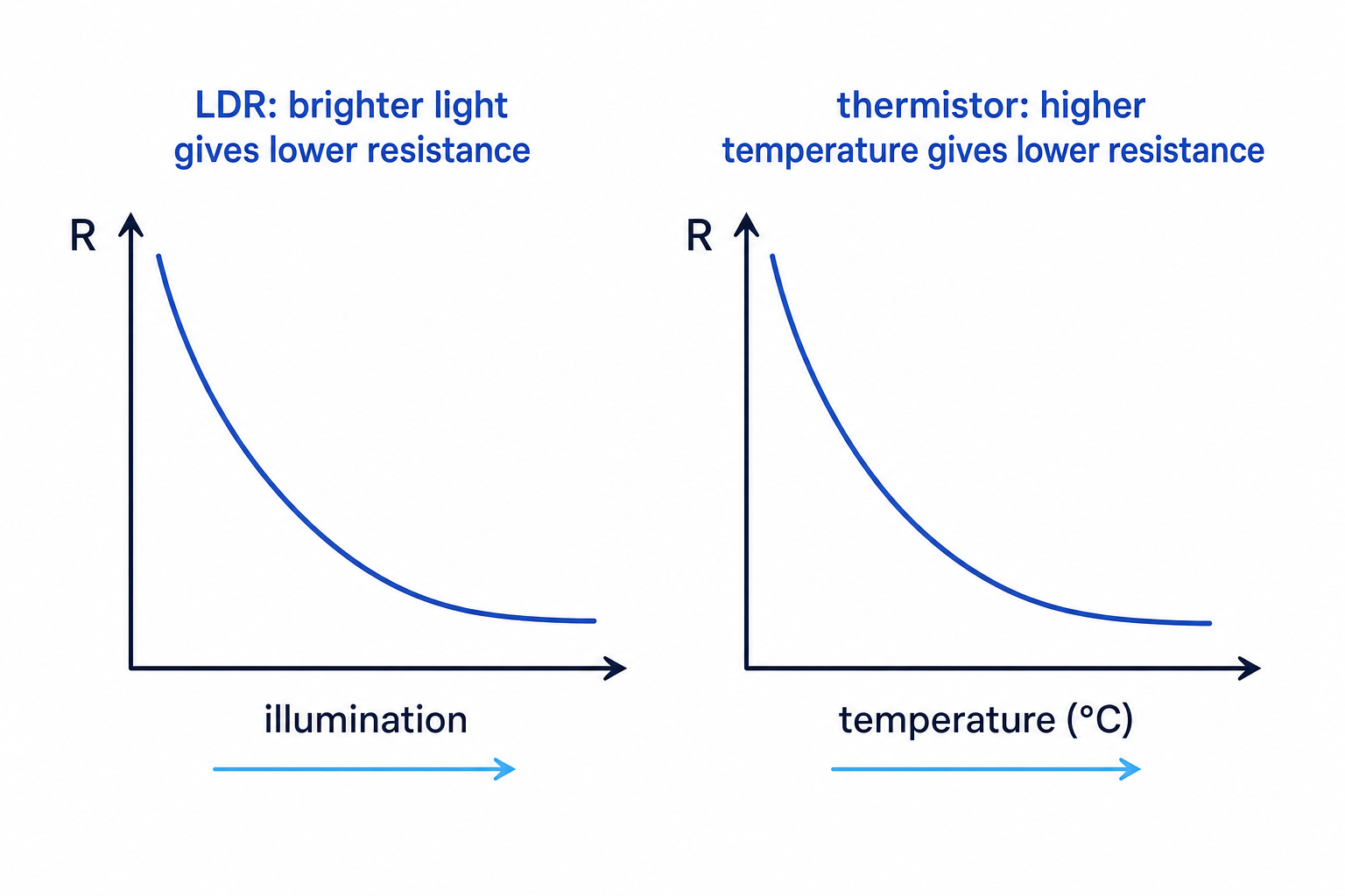
With a fixed supply voltage, lowering the resistance increases the current. That is why LDRs and thermistors are useful in sensing circuits.
9. Energy transferred by charge
Voltage links charge to energy.
Voltage
Voltage is the energy transferred per unit charge passed. One volt is one joule per coulomb.
So a component with a voltage of 6 V transfers 6 J of energy for every coulomb of charge that passes through it.
The spec equation is:
energy transferred = charge × voltage
E=Q×V E = Q \times V E=Q×Vwhere EEE is energy transferred in J, QQQ is charge in C, and VVV is voltage in V.
Calculating charge and energy transferred
A 6.0 V lamp has a current of 0.50 A for 120 s. Calculate the charge that passes and the energy transferred.
- Use the charge equation Q=I×tQ = I \times tQ=I×t:
- Use the energy equation E=Q×VE = Q \times VE=Q×V:
- Interpret the answer: 60 C of charge passes through the lamp, transferring 360 J of energy.
Unit check
A volt is a joule per coulomb, so C multiplied by V gives J. This is a useful check for E=Q×VE = Q \times VE=Q×V.
In the exam
- Decide whether the circuit is series or parallel before choosing rules for current and voltage.
- For calculations, write the equation first, then substitute values with units.
- In current–voltage questions, link graph shape to resistance: straight line means constant resistance; changing gradient means changing resistance.
- For practical questions, always mention ammeter in series, voltmeter in parallel, and plotting current against voltage.
Check yourself
- Why is parallel wiring better than series wiring for domestic lighting?
- What happens to the current in a fixed-voltage circuit if resistance increases?
- How would you recognise a diode from its current–voltage graph?
