

What you'll learn
- How to draw and interpret simple d.c. circuit diagrams using standard symbols.
- How current, potential difference and resistance are connected.
- How series and parallel circuits behave differently.
- How to use I-V graphs and power equations for circuit calculations.
Current, charge and potential difference
A d.c. circuit is a direct current circuit: charge flows in one direction around a complete loop. In circuit diagrams, conventional current is shown flowing from the positive terminal to the negative terminal.
Current and potential difference
Current, symbol III, is the rate of flow of electric charge. It is measured in amperes (A). Potential difference, symbol VVV, is the energy transferred per coulomb of charge between two points. It is measured in volts (V).
Potential difference is often called “voltage” in everyday language. A larger potential difference means each coulomb of charge transfers more energy as it moves through a component.
OCR lists this as a recall-and-apply equation:
E=QVE = QVE=QVwhere EEE is energy transferred in joules (J), QQQ is charge in coulombs (C), and VVV is potential difference in volts (V).
Current is not used up
Current is the flow of charge, so the same charge can keep moving around a complete circuit. Components transfer energy from the charges; they do not “use up” the current.
Calculating energy from charge and potential difference
A 9.0 V battery transfers energy to 20 C of charge. Calculate the energy transferred.
- Choose the potential difference equation because charge and potential difference are given: E=QVE = QVE=QV.
- Substitute the values with units: E=20 C×9.0 VE = 20\ \text{C} \times 9.0\ \text{V}E=20 C×9.0 V.
- Calculate the energy transferred: E=180 JE = 180\ \text{J}E=180 J.
Circuit symbols and measuring instruments
Circuit diagrams use standard symbols so everyone can build the same circuit from the same drawing. A cell supplies a potential difference; the longer line is the positive terminal. A switch opens or closes the circuit. A resistor makes current harder to flow, and a variable resistor lets you change the resistance.
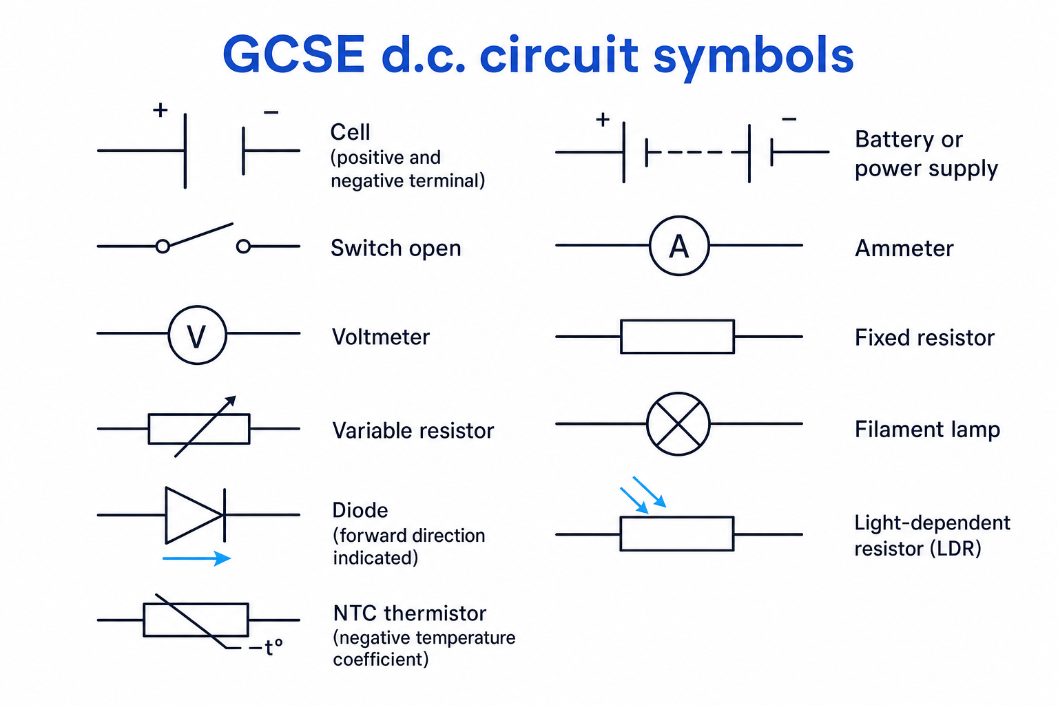
An ammeter measures current and must be connected in series with the component, so the same current flows through the meter and component.
A voltmeter measures potential difference and must be connected in parallel across the component, because it compares the energy per coulomb before and after that component.
Putting meters in the wrong place
Do not put an ammeter across a component like a voltmeter. Ammeters have very low resistance, so connecting one in parallel can create a short circuit.
Resistance and the V = IR relationship
Resistance
Resistance, symbol RRR, is how much a component opposes the flow of current. It is measured in ohms (Ω).
Current depends on both potential difference and resistance:
- increasing potential difference usually increases current
- increasing resistance usually decreases current
OCR lists this as a recall-and-apply equation:
V=IRV = IRV=IRFor a fixed resistor at constant temperature, RRR stays constant. For other components, such as filament lamps, thermistors and diodes, resistance can change as current, temperature or light level changes.
Finding resistance from measurements
A resistor has a potential difference of 6.0 V across it and a current of 0.30 A through it. Calculate its resistance.
- Rearrange the equation to make resistance the subject: R=VIR = \frac{V}{I}R=IV.
- Substitute the measured values: R=6.0 V0.30 AR = \frac{6.0\ \text{V}}{0.30\ \text{A}}R=0.30 A6.0 V.
- Calculate: R=20 ΩR = 20\ \OmegaR=20 Ω.
Series and parallel circuits
A series circuit has one loop, so every component is on the same path. A parallel circuit has branches, giving current more than one route.
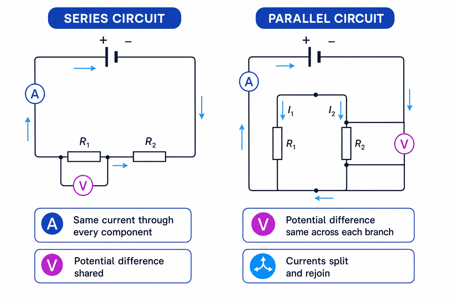
Series and parallel rules
- In series, the current is the same through every component, potential difference is shared, and resistances add.
- In parallel, the potential difference is the same across each branch, currents split and rejoin, and total resistance is reduced.
For resistors in series:
Rtotal=R1+R2+…R_{\text{total}} = R_1 + R_2 + \dotsRtotal=R1+R2+…This increases total resistance because charges have to pass through every resistor in turn.
In parallel, adding another branch gives charge more routes through the circuit. That means the total current from the supply increases, so the overall resistance decreases.
Calculating a series circuit
A 12 V supply is connected to two resistors in series: 4 Ω and 8 Ω. Calculate the total resistance, current and potential difference across each resistor.
- Add the series resistances: Rtotal=4 Ω+8 Ω=12 ΩR_{\text{total}} = 4\ \Omega + 8\ \Omega = 12\ \OmegaRtotal=4 Ω+8 Ω=12 Ω.
- Use V=IRV = IRV=IR for the whole circuit: I=12 V12 Ω=1.0 AI = \frac{12\ \text{V}}{12\ \Omega} = 1.0\ \text{A}I=12 Ω12 V=1.0 A.
- Use the same current through each resistor: V1=1.0 A×4 Ω=4.0 VV_1 = 1.0\ \text{A} \times 4\ \Omega = 4.0\ \text{V}V1=1.0 A×4 Ω=4.0 V and V2=1.0 A×8 Ω=8.0 VV_2 = 1.0\ \text{A} \times 8\ \Omega = 8.0\ \text{V}V2=1.0 A×8 Ω=8.0 V.
Calculating a parallel circuit
A 6.0 V supply is connected to a 3.0 Ω resistor and a 6.0 Ω resistor in parallel. Calculate the branch currents and total resistance.
- Use the parallel rule that each branch has the full supply potential difference: each resistor has 6.0 V across it.
- Calculate each branch current: I1=6.0 V3.0 Ω=2.0 AI_1 = \frac{6.0\ \text{V}}{3.0\ \Omega} = 2.0\ \text{A}I1=3.0 Ω6.0 V=2.0 A and I2=6.0 V6.0 Ω=1.0 AI_2 = \frac{6.0\ \text{V}}{6.0\ \Omega} = 1.0\ \text{A}I2=6.0 Ω6.0 V=1.0 A.
- Add the branch currents: Itotal=2.0 A+1.0 A=3.0 AI_{\text{total}} = 2.0\ \text{A} + 1.0\ \text{A} = 3.0\ \text{A}Itotal=2.0 A+1.0 A=3.0 A.
- Use the total current to find total resistance: Rtotal=6.0 V3.0 A=2.0 ΩR_{\text{total}} = \frac{6.0\ \text{V}}{3.0\ \text{A}} = 2.0\ \OmegaRtotal=3.0 A6.0 V=2.0 Ω, which is lower than either branch resistor.
Using series rules in parallel circuits
In parallel circuits, do not share out the potential difference between branches. Each branch gets the same potential difference as the supply.
Components that change resistance
Some components are linear, meaning their I-V graph is a straight line through the origin. This shows current is directly proportional to potential difference.
Other components are non-linear, meaning the graph is curved because resistance changes.
To investigate this, you build a test circuit with:
- the component being tested
- an ammeter in series
- a voltmeter across the component
- a variable resistor or variable power supply to change the potential difference
This is the basic idea behind PAG P6-style circuit investigations.
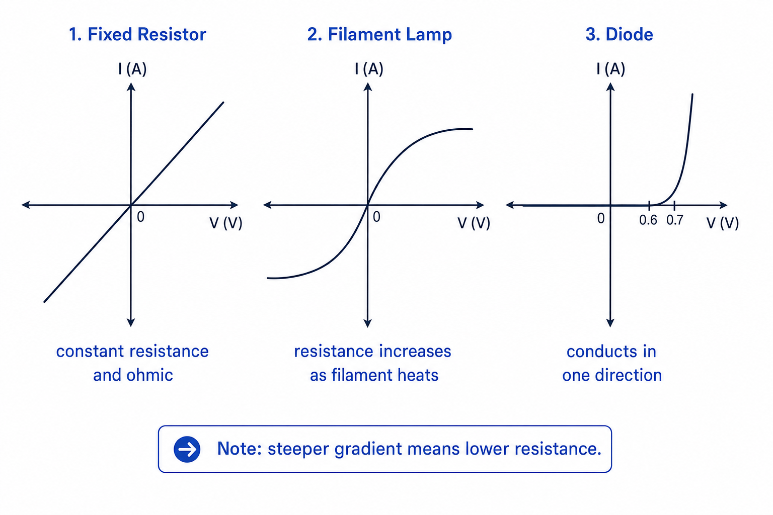
For an I-V graph with current on the vertical axis and potential difference on the horizontal axis, the gradient is linked to I÷VI \div VI÷V. A steeper graph means a larger current for the same potential difference, so the resistance is lower.
Component behaviour to know:
- Fixed resistor: straight I-V graph through the origin; resistance is constant.
- Filament lamp: as current increases, the filament heats up, so resistance increases and the graph becomes less steep.
- Diode: current flows easily in one direction only after a forward potential difference is reached; reverse current is very small.
- NTC thermistor: resistance decreases as temperature increases.
- LDR: resistance decreases as light intensity increases.
Interpreting an I-V graph
A component has current 0.40 A at 2.0 V, but current 0.80 A at 6.0 V. Decide whether its resistance is constant.
- Calculate the resistance at 2.0 V: R=2.0 V0.40 A=5.0 ΩR = \frac{2.0\ \text{V}}{0.40\ \text{A}} = 5.0\ \OmegaR=0.40 A2.0 V=5.0 Ω.
- Calculate the resistance at 6.0 V: R=6.0 V0.80 A=7.5 ΩR = \frac{6.0\ \text{V}}{0.80\ \text{A}} = 7.5\ \OmegaR=0.80 A6.0 V=7.5 Ω.
- Compare the two values: the resistance has increased, so the component is non-linear.
Non-ohmic components
Do not assume resistance is constant for a filament lamp, diode, thermistor or LDR. Use R=VIR = \frac{V}{I}R=IV at the operating point you are given.
Power and energy in circuits
Power
Power, symbol PPP, is the rate of energy transfer. It is measured in watts (W), where 1 W means 1 J of energy transferred per second.
OCR lists these power equations as recall-and-apply:
P=VIP=I2R\begin{aligned} P &= VI \\ P &= I^2R \end{aligned}PP=VI=I2REnergy transferred over time is also recall-and-apply:
E=PtE = PtE=PtUse matching units:
- if power is in watts (W) and time is in seconds (s), energy is in joules (J)
- if power is in kilowatts (kW) and time is in hours (h), energy is in kilowatt-hours (kW h)
Kilowatt-hours
A kilowatt-hour is a unit of energy, not power. 1 kW h=3.6×10⁶ J1\ \text{kW h} = 3.6 \times 10^6\ \text{J}1 kW h=3.6×10⁶ J.
Calculating power and energy
A 6.0 V motor has a current of 0.50 A for 120 s. Calculate its power and energy transferred.
- Use the power equation with potential difference and current: P=VI=6.0 V×0.50 A=3.0 WP = VI = 6.0\ \text{V} \times 0.50\ \text{A} = 3.0\ \text{W}P=VI=6.0 V×0.50 A=3.0 W.
- Use energy equals power times time: E=Pt=3.0 W×120 s=360 JE = Pt = 3.0\ \text{W} \times 120\ \text{s} = 360\ \text{J}E=Pt=3.0 W×120 s=360 J.
- If the motor’s resistance were 12 Ω, the resistor power equation gives the same result: P=I2R=(0.50 A)2×12 Ω=3.0 WP = I^2R = (0.50\ \text{A})^2 \times 12\ \Omega = 3.0\ \text{W}P=I2R=(0.50 A)2×12 Ω=3.0 W.
In the exam
- Mark whether components are in series or parallel before calculating: series means same current; parallel means same potential difference.
- Write the equation, substitute with units, then calculate — especially for V=IRV = IRV=IR, E=QVE = QVE=QV, P=VIP = VIP=VI, P=I2RP = I^2RP=I2R and E=PtE = PtE=Pt.
- Check your answer makes sense: adding resistors in series should increase total resistance, while adding branches in parallel should decrease it.
Check yourself
- Where should an ammeter and voltmeter be placed when measuring a resistor?
- How do current and potential difference behave differently in series and parallel circuits?
- Why is the I-V graph of a filament lamp curved rather than a straight line?
