2.2.1a Series circuits
Series circuits: one loop, one path for the charge
Definition
Series circuit
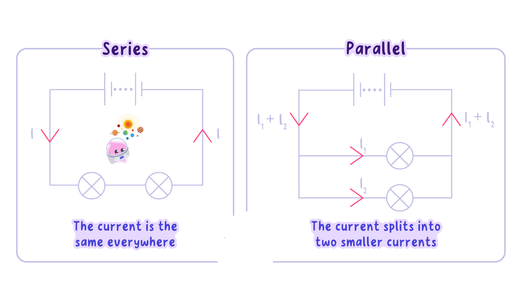
A series circuit is one in which the components are connected one after another in a single loop, so there is only one path for the charge.
- Because there is only one path, the charge cannot split between routes, and this gives three rules: the current is the same everywhere, the supply potential difference is shared, and the resistances add up.
The current is the same through every component
- In a series circuit the current is the same through every component.
- Current is the rate of flow of charge, and in a single loop the same charge passes through each component in turn; charge is not used up, so the current does not shrink as it goes round.
- For example, if the current through one lamp is 0.30 A0.30\ \text{A}0.30 A, it is 0.30 A0.30\ \text{A}0.30 A through every component in that loop.
The supply potential difference is shared
- The supply provides a total potential difference that is shared between the components: Vsupply=V1+V2+…V_\text{supply} = V_1 + V_2 + \dotsVsupply=V1+V2+…
- As the charge passes through each component it transfers energy to it, and the potential differences across the components add up to the supply potential difference.
- For example, a 12 V12\ \text{V}12 V supply across two lamps in series might give 5 V5\ \text{V}5 V across one and 7 V7\ \text{V}7 V across the other, which add to 12 V12\ \text{V}12 V.
Resistances add, so more resistors mean more resistance
- The total resistance of resistors in series is the sum of the separate resistances: Rtotal=R1+R2+…R_\text{total} = R_1 + R_2 + \dotsRtotal=R1+R2+…, in ohms, Ω\OmegaΩ.
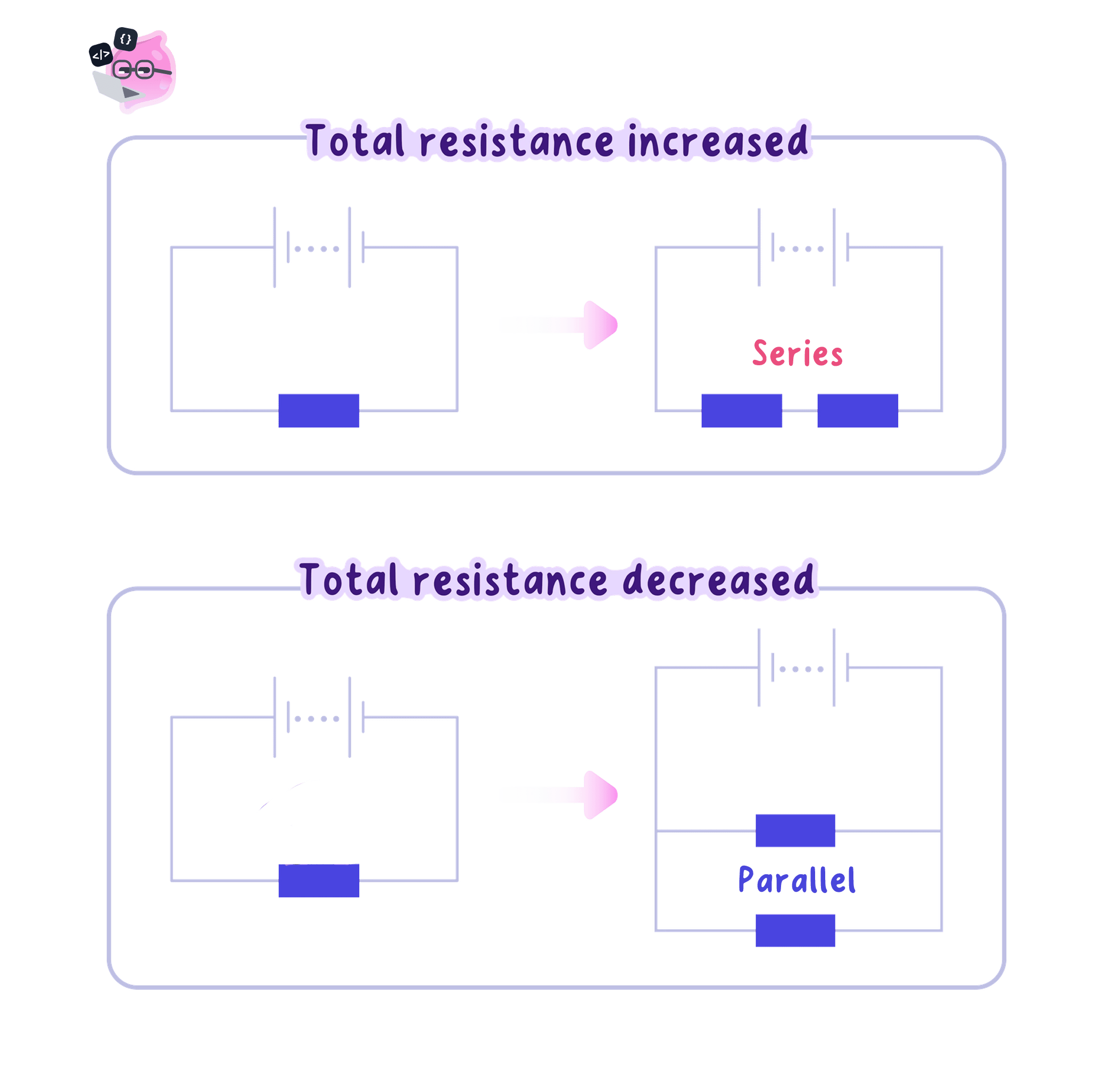
- Adding a resistor in series adds more opposition to the flow of charge, because all the charge must pass through every resistor.
- For the same supply potential difference, a larger total resistance gives a smaller current.
- A d.c. series circuit is useful for measurement and testing because the current is the same everywhere: an ammeter in series reads the current through the component, and a lamp in series lights only when there is a complete conducting path.
- To solve a series circuit, first replace the series resistors with their equivalent resistance, a single resistance with the same effect, then use V=IRV = IRV=IR.
Example
- A 12 V12\ \text{V}12 V d.c. supply is connected to a 4 Ω4\ \Omega4 Ω resistor and an 8 Ω8\ \Omega8 Ω resistor in series. Find the total resistance, the current, and the potential difference across each resistor.
- Add the resistances:
- Find the current with V=IRV = IRV=IR:
- The current is the same through both resistors, so it is 1.0 A1.0\ \text{A}1.0 A through each.
- Find each potential difference:
- The two potential differences add to 12 V12\ \text{V}12 V, which matches the supply, so the answer is sensible.
Common Mistake
- Do not say the current is "shared" or "used up" in a series circuit: it is the same through every component.
- It is the supply potential difference that is shared, and the potential differences across the components add up to it.
Exam technique
- Write the series rules before you calculate: the current is the same, the potential differences add, and the resistances add.
- For a calculation, find the equivalent resistance of the series resistors first, then use V=IRV = IRV=IR, with A\text{A}A, V\text{V}V and Ω\OmegaΩ in your answers.
Self review
- How many paths for charge are there in a series circuit?
- What is true about the current through each component in series?
- How are the potential differences across series components related to the supply?
- How do you find the total resistance of resistors in series?
- Why does adding a resistor in series reduce the current for the same supply?
2.2.1b Parallel circuits
Parallel circuits: separate branches, more than one path
Definition
Parallel circuit
A parallel circuit is one in which components are connected on separate branches, so the charge has more than one path to take.
- Each branch is joined directly across the same two points of the supply, so every branch gets the same potential difference as the supply, as long as the wires have negligible resistance.
- Parallel circuits have three rules: the potential difference across each branch is the same, the branch currents add to the total current, and the total resistance is less than the smallest single resistor.
Key Idea
In a parallel circuit the branches share the same potential difference, but the current splits between them.
The potential difference is the same across every branch
- In a parallel circuit the potential difference across each branch is the same, because each branch is joined directly to the same two terminals of the supply.
- For example, a 6 V6\ \text{V}6 V battery with two lamps in parallel puts 6 V6\ \text{V}6 V across each lamp.
- This differs from a series circuit, where the supply potential difference is shared between the components.
The branch currents add up to the total current
- At a junction the current splits between the branches, and where the branches rejoin the currents add back together: Itotal=I1+I2+…I_\text{total} = I_1 + I_2 + \dotsItotal=I1+I2+…
- This is because charge is conserved: the charge flowing into a junction each second equals the charge flowing out of it.
Example
- A parallel circuit has three branches carrying 0.20 A0.20\ \text{A}0.20 A, 0.35 A0.35\ \text{A}0.35 A and 0.15 A0.15\ \text{A}0.15 A. Find the total current from the supply.
- The total current from the supply is 0.70 A0.70\ \text{A}0.70 A.
Adding a parallel branch lowers the total resistance
- Adding a resistor in parallel gives the charge an extra path, so more current flows from the supply for the same potential difference, which means the total resistance has decreased.
- The total resistance of two resistors in parallel is less than the resistance of the smaller one.
- You are not expected to calculate the total resistance of resistors in parallel; the key skill is the qualitative explanation, that more branches give more paths for the charge, so the resistance falls.
Common Mistake
- Do not say the current is "used up": it splits between branches, but charge is conserved.
- Do not say adding a resistor always increases resistance: it increases the total in series but decreases the total in parallel.
Reading a parallel circuit, and why it is useful
- To spot a parallel circuit, look for branches: components connected across the same two points.
- When you check a parallel circuit diagram, look for these things:
- each branch forms a complete conducting path
- each branch is connected across the same two points of the supply
- an ammeter is in series with the component or branch it measures
- a voltmeter is in parallel across the component it measures
- switches can be placed to control the whole circuit or just one branch
- If one branch breaks, components on the other complete branches still work, which is why household lighting uses parallel circuits: one lamp can fail or be switched off without stopping the others.
- In short, a series circuit keeps the current the same but shares the potential difference, while a parallel circuit keeps the potential difference the same but splits the current.
Exam technique
- Learn the precise phrases: the potential difference across each branch is the same, and the total current is the sum of the branch currents.
- For "why" questions, link your answer to branches and paths for the charge, for example: adding a resistor in parallel gives another path, so the total resistance decreases.
Self review
- How are components connected in a parallel circuit?
- What is true about the potential difference across each parallel branch?
- How is the total current related to the branch currents?
- What happens to the total resistance when you add a resistor in parallel, and why?
- Why does household lighting use parallel circuits?
