2.1.4a Resistors: ohmic conductors
Resistance can stay constant or change as the current changes
Resistance
Resistance is a measure of how difficult it is for current to flow through a component. It is measured in ohms, Ω\OmegaΩ.
- The resistance of a component is found from R=VIR = \dfrac{V}{I}R=IV, where VVV is the potential difference in volts and III is the current in amperes.
- For some components the resistance stays constant as the current changes; for others it changes.
- You can test which is true by checking whether the ratio VI\dfrac{V}{I}IV stays the same at different currents.
- A resistor has 2.0 V2.0\ \text{V}2.0 V across it and 0.40 A0.40\ \text{A}0.40 A through it. When the potential difference is raised to 6.0 V6.0\ \text{V}6.0 V, the current becomes 1.20 A1.20\ \text{A}1.20 A. Show that the resistance is constant.
- The resistance is 5.0 Ω5.0\ \Omega5.0 Ω both times, so it is constant.
Ohmic conductors: current is proportional to potential difference
Ohmic conductor
An ohmic conductor is a component whose current is directly proportional to the potential difference across it, provided its temperature stays constant.
- For an ohmic conductor at constant temperature, I∝VI \propto VI∝V.
- So if the potential difference doubles, the current doubles, and because VI\dfrac{V}{I}IV stays the same, the resistance stays constant.
- The words at constant temperature\textbf{at constant temperature}at constant temperature matter: if the temperature changes, the resistance can change and the simple proportional relationship no longer holds.
- On a graph of current against potential difference, an ohmic conductor gives a straight line through the origin.
For an ohmic conductor at constant temperature:
- the current is directly proportional to the potential difference
- the resistance stays constant
- the ratio VI\dfrac{V}{I}IV stays the same
- the III–VVV graph is a straight line through the origin.
Many components do not have constant resistance
- The resistance of lamps, diodes, thermistors and light-dependent resistors is not constant: it changes as the current through the component changes.
- So the current is not directly proportional to the potential difference, and R=VIR = \dfrac{V}{I}R=IV gives a different value at different currents.
- You do not call these components ohmic conductors, because their resistance does not stay constant.
- A component has 3.0 V3.0\ \text{V}3.0 V across it and 0.50 A0.50\ \text{A}0.50 A through it. When the potential difference is raised to 6.0 V6.0\ \text{V}6.0 V, the current becomes 0.75 A0.75\ \text{A}0.75 A. Is its resistance constant?
- The resistance changes from 6.0 Ω6.0\ \Omega6.0 Ω to 8.0 Ω8.0\ \Omega8.0 Ω, so it is not constant and the component is not ohmic.
- Do not say an ohmic conductor has a constant current: the current can change.
- It is the resistance that stays constant, so the current changes in direct proportion to the potential difference.
- Direct proportionality only holds for an ohmic conductor if the temperature is constant.
- Link the three ideas together: at constant temperature the current is directly proportional to the potential difference, so VI\dfrac{V}{I}IV, and therefore the resistance, stays constant.
- For a graph, a straight line through the origin is the sign of an ohmic conductor.
- How do you calculate the resistance of a component from readings of potential difference and current?
- What is an ohmic conductor?
- What condition must hold for a conductor to stay ohmic?
- What shape is the III–VVV graph of an ohmic conductor?
- Name three components that do not have constant resistance.
2.1.4b Resistors: filament lamp and diode
A filament lamp's resistance rises as it heats up
Filament lamp
A filament lamp is a component that gives out light when a current heats its thin metal filament.
- The resistance of a filament lamp is not constant: it increases as the filament gets hotter.
- When current passes through the filament, energy is transferred to it electrically, so the filament becomes very hot and emits light.
- As the filament heats up, its metal ions vibrate more, which makes it harder for the electrons to pass through, so the resistance increases.
- So as the potential difference is increased, the current rises at first, but the increasing resistance means the current does not increase in direct proportion to the potential difference.
A diode lets current flow one way only
Diode
A diode is a component that allows current to flow through it in one direction only.
- In its forward direction a diode has a low resistance\textbf{low resistance}low resistance, so current flows easily.
- In the reverse direction it has a very high resistance\textbf{very high resistance}very high resistance, so almost no current flows.
- A diode therefore acts as a one-way device: to decide whether current flows, check which way the diode is connected, and if it is reversed the current is zero or very small.
- Do not say a filament lamp has a fixed resistance: its resistance rises as its temperature rises.
- Do not say a diode "uses up" or "stores" current: it allows current one way only and has a very high resistance in reverse.
- For a filament lamp, give the causal chain: current increases, filament gets hotter, resistance increases, so the current increases less.
- For a diode, the marking phrases are one direction only and very high resistance in the reverse direction.
- What happens to the resistance of a filament lamp as it gets hotter, and why?
- Why does the current through a filament lamp not increase in direct proportion to the potential difference?
- In which direction does a diode let current flow?
- What is the resistance of a diode in the reverse direction?
- What happens to the current if a diode is connected in reverse?
2.1.4c Resistors: thermistors, LDRs and I–V characteristics (required practical)
A thermistor's resistance falls as it gets hotter
Thermistor
A thermistor is a resistor whose resistance decreases as its temperature increases.
- As a thermistor gets hotter its resistance falls, so for a fixed potential difference the current through it increases.
- This makes thermistors useful in temperature-sensing circuits such as thermostats.
- In a thermostat, a rise in temperature lowers the thermistor’s resistance, and a control circuit uses this change to switch a heater off or switch cooling on.
An LDR's resistance falls as the light gets brighter
Light-dependent resistor (LDR)
A light-dependent resistor is a resistor whose resistance decreases as the light intensity on it increases.
- In bright light an LDR has a low resistance; in dim light or darkness it has a high resistance.
- This makes LDRs useful in light-sensing circuits such as automatic street lights.
- When it gets dark, the light on the LDR falls and its resistance rises, and the control circuit uses this change to switch the lamp on.
Measuring the resistance of a component
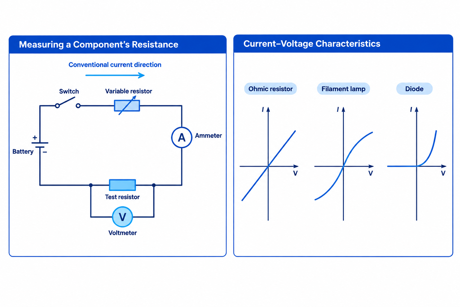
- To measure a component’s resistance, measure the current through it with an ammeter in series and the potential difference across it with a voltmeter in parallel, then use R=VIR = \dfrac{V}{I}R=IV in ohms, Ω\OmegaΩ.
- A suitable circuit has a cell, battery or d.c. supply, a switch, an ammeter in series with the component, the component itself, a voltmeter in parallel across it, and usually a variable resistor in series so the current and potential difference can be changed.
- Use the correct symbols: a resistor is a rectangle, a thermistor is a resistor with a diagonal line ending in a short bar, and an LDR is a resistor in a circle with arrows pointing towards it.
- The potential difference across a thermistor is 3.0 V3.0\ \text{V}3.0 V and the current through it is 0.015 A0.015\ \text{A}0.015 A. Calculate its resistance.
- The resistance of the thermistor is 200 Ω200\ \Omega200 Ω.
I–V characteristics identify a component by the shape of its graph
- An I–V characteristic is a graph of the current through a component against the potential difference across it, and its shape tells you how the component behaves.
- You obtain the characteristic by changing the potential difference across the component and recording pairs of current and potential difference readings.
Investigation: the I–V characteristics of a resistor, a filament lamp and a diode
Apparatus
- a digital ammeter, and a milliammeter for the diode because only a small current flows through it
- a digital voltmeter
- a variable resistor
- the components to test: a resistor, a filament lamp, and a diode with a protective resistor in series
- a battery or d.c. power supply and connecting leads
Method
- Build a series circuit of the power supply, the ammeter, the component under test and the variable resistor, with the voltmeter connected in parallel across the component.
- Adjust the variable resistor to change the potential difference, and record a pair of current and potential difference readings.
- Repeat to collect several pairs of readings across the range.
- Swap the connections to the power supply so the readings become negative, and record several more pairs.
- Plot current on the vertical axis against potential difference on the horizontal axis; because there are negative values, the origin sits in the middle of the paper.
- Repeat for each component in turn: the resistor at constant temperature, the filament lamp, and the diode.
Working safely and accurately
- Keep the potential difference low enough not to damage the components, and check their ratings first.
- The diode needs a protective resistor in series to limit the current, and a milliammeter to read the small current through it.
Results: what each graph looks like
- Resistor at constant temperature: a straight line through the origin, so the current is directly proportional to the potential difference and the resistance is constant.
- Filament lamp: an S-shaped curve that becomes less steep as the potential difference rises, because the filament heats up and its resistance increases.
- Diode: current flows in the forward direction once a small forward potential difference is reached, and almost none flows in reverse because the reverse resistance is very high.
- Do not mix up the relationships: a thermistor and an LDR both drop in resistance (hotter, or brighter), but a filament lamp rises in resistance as it gets hotter.
- The ammeter goes in series and the voltmeter goes in parallel; swapping them is a common circuit-diagram error.
- For a graph question, do not just say "the line goes up": say what the shape means.
- A straight line through the origin means constant resistance; a curve means the resistance changes, and for a filament lamp you link that to the filament heating up.
- What happens to a thermistor’s resistance as its temperature rises?
- What happens to an LDR’s resistance as the light gets brighter?
- Where do the ammeter and voltmeter go in a circuit to measure resistance?
- What shape is the I–V graph of a resistor at constant temperature?
- Why does the I–V graph of a filament lamp curve?