

What you'll learn
- How resistance and resistivity are different.
- How to use R=ρL/AR = \rho L/AR=ρL/A and ρ=RA/L\rho = RA/Lρ=RA/L for a uniform wire.
- How to determine the resistivity of a metal experimentally.
- Why metals, semiconductors and NTC thermistors behave differently as temperature changes.
Prerequisites: resistance, current and potential difference
Current is the rate of flow of electric charge, measured in amperes, A. In a metal wire, the moving charge carriers are electrons.
Potential difference is the energy transferred per unit charge between two points, measured in volts, V.
Resistance is how much a component opposes current. It is measured in ohms, Ω, and is defined using:
V=IRV = IRV=IRwhere VVV is potential difference, III is current, and RRR is resistance.
A component’s resistance can change if its material, length, cross-sectional area, or temperature changes. Resistivity is the quantity that focuses on the material itself.
Resistance depends on more than the material
Two wires made of the same metal can have different resistances if they have different lengths or thicknesses. Resistivity lets you compare materials fairly, provided temperature is specified.
Resistivity: the material property
Resistivity tells you how strongly a material resists electric current, independent of the particular length and thickness of the sample.
Resistivity
For a uniform conductor at constant temperature, resistivity ρ\rhoρ is defined by:
ρ=RAL\rho = \frac{RA}{L}ρ=LRAEquivalently:
R=ρLAR = \frac{\rho L}{A}R=AρLwhere RRR is resistance, LLL is length, and AAA is cross-sectional area. The unit of resistivity is the ohm metre, Ω m.
For a wire of the same material at constant temperature:
- increasing the length increases resistance: R∝LR \propto LR∝L
- increasing the cross-sectional area decreases resistance: R∝1/AR \propto 1/AR∝1/A
The cross-sectional area is the area you would see if you cut straight across the wire. For a circular wire of diameter ddd:
A=πd24A = \frac{\pi d^2}{4}A=4πd2Diameter is not radius
If you measure the diameter ddd with a micrometer, use A=πd2/4A = \pi d^2/4A=πd2/4. Do not put the diameter into A=πr2A = \pi r^2A=πr2 unless you first halve it to get the radius.
Calculating resistance from resistivity
A constantan wire has resistivity 4.9×10⁻⁷ Ω m4.9 \times 10^{-7}\,\Omega\,\text{m}4.9×10⁻⁷Ωm, length 1.50 m1.50\,\text{m}1.50m, and diameter 0.40 mm0.40\,\text{mm}0.40mm. Calculate its resistance.
-
Convert the diameter to metres and calculate the cross-sectional area:
d=0.40 mm=4.0×10⁻⁴ md = 0.40\,\text{mm} = 4.0 \times 10^{-4}\,\text{m}d=0.40mm=4.0×10⁻⁴m A=πd24=π(4.0×10⁻⁴ m)24=1.26×10⁻⁷ m2A = \frac{\pi d^2}{4} = \frac{\pi(4.0 \times 10^{-4}\,\text{m})^2}{4} = 1.26 \times 10^{-7}\,\text{m}^2A=4πd2=4π(4.0×10⁻⁴m)2=1.26×10⁻⁷m2 -
Choose the resistivity equation in the form needed for resistance:
R=ρLAR = \frac{\rho L}{A}R=AρL -
Substitute values, carrying the units through:
R=(4.9×10⁻⁷ Ω m)(1.50 m)1.26×10⁻⁷ m2=5.85 ΩR = \frac{(4.9 \times 10^{-7}\,\Omega\,\text{m})(1.50\,\text{m})} {1.26 \times 10^{-7}\,\text{m}^2} = 5.85\,\OmegaR=1.26×10⁻⁷m2(4.9×10⁻⁷Ωm)(1.50m)=5.85ΩTo two significant figures, the resistance is 5.9 Ω.
Determining the resistivity of a metal wire
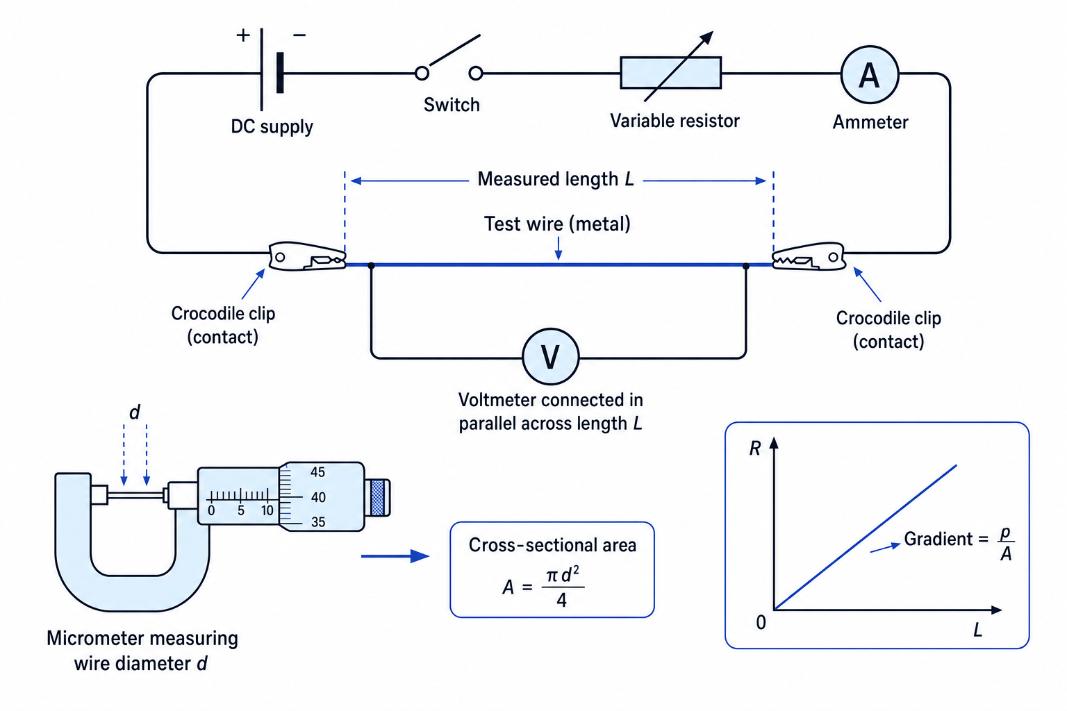
A typical practical uses a long, thin metal wire, a power supply, an ammeter, a voltmeter, and a micrometer. You measure the resistance of different lengths of the same wire, then use a graph to find ρ\rhoρ.
The diagram below shows the key idea: measure the potential difference across only the chosen length LLL, measure the current through the wire, and measure the wire diameter separately.
Practical method
- Use a metre rule to measure the length LLL of wire between the voltage contacts.
- Use a micrometer to measure the diameter ddd at several points along the wire, rotating the wire between readings.
- Calculate the mean diameter, then calculate A=πd2/4A = \pi d^2/4A=πd2/4.
- Set up the circuit with the ammeter in series and the voltmeter in parallel across the measured length of wire.
- Use a low current and close the switch only while taking readings, so the wire does not heat up significantly.
- Record VVV and III, then calculate R=V/IR = V/IR=V/I.
- Repeat for several different lengths of wire.
- Plot a graph of RRR against LLL.
From:
R=ρALR = \frac{\rho}{A}LR=AρLthe graph of RRR against LLL should be a straight line. Its gradient is:
gradient=ΔRΔL=ρA\text{gradient} = \frac{\Delta R}{\Delta L} = \frac{\rho}{A}gradient=ΔLΔR=Aρso:
ρ=gradient×A\rho = \text{gradient} \times Aρ=gradient×AWhy the graph method is better
Using a best-fit line uses all your readings, reduces the effect of random error, and can reveal systematic issues such as contact resistance if the graph has a noticeable intercept.
Keep the wire at constant temperature
The equation R=ρL/AR = \rho L/AR=ρL/A assumes the resistivity is constant. If the current heats the wire, ρ\rhoρ changes, so your calculated resistivity becomes less reliable.
Finding resistivity from a graph
A student plots RRR against LLL for a metal wire. The best-fit gradient is 4.3 Ω per metre. The mean diameter of the wire is 0.38 mm0.38\,\text{mm}0.38mm. Calculate the resistivity.
-
Convert the diameter and calculate the area:
d=0.38 mm=3.8×10⁻⁴ md = 0.38\,\text{mm} = 3.8 \times 10^{-4}\,\text{m}d=0.38mm=3.8×10⁻⁴m A=π(3.8×10⁻⁴ m)24=1.13×10⁻⁷ m2A = \frac{\pi(3.8 \times 10^{-4}\,\text{m})^2}{4} = 1.13 \times 10^{-7}\,\text{m}^2A=4π(3.8×10⁻⁴m)2=1.13×10⁻⁷m2 -
Use the gradient relationship:
ρ=gradient×A\rho = \text{gradient} \times Aρ=gradient×A -
Substitute and simplify the units:
ρ=(4.3 Ω m−1)(1.13×10⁻⁷ m2)=4.9×10⁻⁷ Ω m\rho = (4.3\,\Omega\,\text{m}^{-1})(1.13 \times 10^{-7}\,\text{m}^2) = 4.9 \times 10^{-7}\,\Omega\,\text{m}ρ=(4.3Ωm−1)(1.13×10⁻⁷m2)=4.9×10⁻⁷ΩmThe resistivity is 4.9×10⁻⁷ Ω m4.9 \times 10^{-7}\,\Omega\,\text{m}4.9×10⁻⁷Ωm.
How temperature affects resistivity
A charge carrier is a charged particle that can move through a material and carry current.
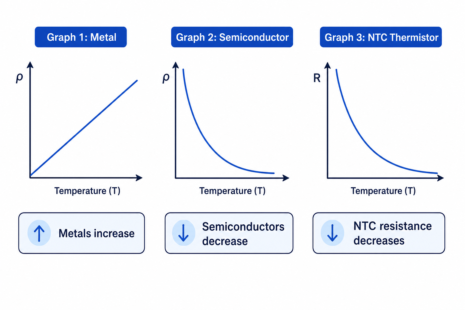
In a metal, the charge carriers are electrons moving through a lattice of positive ions. As temperature increases, the ions vibrate more strongly. The electrons collide with the vibrating lattice more often, so the resistivity of the metal increases.
A semiconductor is a material with electrical behaviour between a conductor and an insulator. In semiconductors, increasing temperature creates many more mobile charge carriers. This effect dominates, so the resistivity decreases as temperature increases.
The graph shapes below are the important ones to recognise and explain.
Opposite temperature trends
For metals, increasing temperature usually increases resistivity. For semiconductors, increasing temperature usually decreases resistivity because the number of charge carriers increases.
Predicting current changes when components are heated
A metal wire and a semiconductor component are each connected across the same fixed potential difference. Predict what happens to the current in each when they are warmed.
-
For the metal, warming increases lattice vibrations, so the resistivity and resistance increase.
-
With the same potential difference, use I=V/RI = V/RI=V/R: if RRR increases, the current decreases.
-
For the semiconductor, warming produces many more charge carriers, so the resistance decreases. With the same potential difference, the current increases.
NTC thermistors
A thermistor is a resistor whose resistance depends strongly on temperature.
NTC thermistor
An NTC thermistor is a temperature-dependent resistor with a negative temperature coefficient, meaning its resistance decreases as its temperature increases.
NTC thermistors are usually made from semiconductor materials. Their resistance-temperature graph is non-linear: resistance falls rapidly over some temperature ranges and then changes more gradually.
They are useful in temperature sensors because a small temperature change can produce a measurable resistance change. For example, they can be used in electronic thermometers, thermostats, and temperature-controlled circuits.
NTC does not behave like a metal wire
A metal wire usually has resistance that increases when it gets hotter. An NTC thermistor does the opposite: its resistance decreases when it gets hotter.
Using an NTC thermistor trend
An NTC thermistor is connected across a fixed potential difference of 6.0 V6.0\,\text{V}6.0V. Its resistance is 12 kΩ12\,\text{k}\Omega12kΩ at a lower temperature and 3.0 kΩ3.0\,\text{k}\Omega3.0kΩ at a higher temperature. Calculate the current in each case.
-
At the lower temperature, convert the resistance and calculate the current:
R=12 kΩ=1.2×10⁴ ΩR = 12\,\text{k}\Omega = 1.2 \times 10^4\,\OmegaR=12kΩ=1.2×10⁴Ω I=VR=6.0 V1.2×104 Ω=5.0×10⁻⁴ AI = \frac{V}{R} = \frac{6.0\,\text{V}}{1.2 \times 10^4\,\Omega} = 5.0 \times 10^{-4}\,\text{A}I=RV=1.2×10⁴Ω6.0V=5.0×10⁻⁴A -
At the higher temperature:
R=3.0 kΩ=3.0×10³ ΩR = 3.0\,\text{k}\Omega = 3.0 \times 10^3\,\OmegaR=3.0kΩ=3.0×10³Ω I=6.0 V3.0×103 Ω=2.0×10⁻³ AI = \frac{6.0\,\text{V}}{3.0 \times 10^3\,\Omega} = 2.0 \times 10^{-3}\,\text{A}I=3.0×10³Ω6.0V=2.0×10⁻³A -
Compare the currents: the current increases from 0.50 mA0.50\,\text{mA}0.50mA to 2.0 mA2.0\,\text{mA}2.0mA because the thermistor’s resistance has decreased as temperature increased.
In the exam
-
Always distinguish resistance RRR from resistivity ρ\rhoρ: resistance depends on size and shape, but resistivity is a material property at a stated temperature.
-
For wire questions, convert diameter to metres and calculate area using A=πd2/4A = \pi d^2/4A=πd2/4 before using R=ρL/AR = \rho L/AR=ρL/A.
-
For practical questions, describe the graph method: calculate R=V/IR = V/IR=V/I, plot RRR against LLL, use the gradient, and mention keeping the wire cool to keep temperature constant.
Check yourself
- Why does doubling the length of a wire double its resistance, but doubling its diameter does not simply double its resistance?
- How would you use a graph of RRR against LLL to find the resistivity of a metal wire?
- Why does the resistivity of a semiconductor decrease when its temperature increases?
