

What you'll learn
- How resistance links potential difference and current.
- What Ohm’s law really says, especially the constant-temperature condition.
- How to recognise I–V characteristics for resistors, lamps, thermistors, diodes and LEDs.
- How to investigate electrical components and interpret your data.
Starting point: current and potential difference
An electric current, III, is the flow of charge through a point in a circuit per second. It is measured in amperes, A.
Potential difference, VVV, is the energy transferred by each coulomb of charge between two points. It is measured in volts, V. A potential difference across a component “pushes” charge through it, but the size of the current depends on the component.
Resistance
Resistance, RRR, tells you how strongly a component opposes the flow of current. A larger resistance means a smaller current for the same potential difference.
Resistance
Resistance is defined by the ratio of the potential difference across a component to the current through it:
R=VIR = \frac{V}{I}R=IVRearranging gives the very useful circuit equation:
V=IRV = IRV=IRThe unit of resistance is the ohm, symbol Ω\OmegaΩ. One ohm means one volt per ampere:
1 Ω=1 V A−11\ \Omega = 1\ \text{V A}^{-1}1 Ω=1 V A−1You are expected to recall R=V/IR = V/IR=V/I.
Calculating resistance
A sensor has a potential difference of 3.0 V across it and a current of 2.5 mA through it. Calculate its resistance.
-
Convert the current into amperes:
2.5 mA=2.5×10⁻³ A2.5\ \text{mA} = 2.5 \times 10^{-3}\ \text{A}2.5 mA=2.5×10⁻³ A -
Substitute into R=V/IR = V/IR=V/I:
R=3.0 V2.5×10−3 A=1.2×10³ ΩR = \frac{3.0\ \text{V}}{2.5 \times 10^{-3}\ \text{A}} = 1.2 \times 10^{3}\ \OmegaR=2.5×10⁻³ A3.0 V=1.2×10³ Ω -
Express the answer using a sensible prefix:
R=1.2 kΩR = 1.2\ \text{k}\OmegaR=1.2 kΩ
Ohm’s law
Ohm’s law is about how current changes when potential difference changes.
Ohm’s law
For an ohmic conductor at constant temperature, the current through the conductor is directly proportional to the potential difference across it.
“Directly proportional” means that if you double the potential difference, the current doubles. The resistance stays constant.
A component that obeys Ohm’s law is called ohmic. A component whose resistance changes as the current or potential difference changes is non-ohmic.
Ohm’s law is not just V = IR
The equation V=IRV = IRV=IR can be used to define resistance at an operating point. Ohm’s law is the extra statement that RRR stays constant as VVV and III change, provided temperature and other physical conditions stay constant.
Testing whether a component is ohmic
A component gives these readings: 2.0 V and 0.10 A; 4.0 V and 0.20 A; 6.0 V and 0.30 A. Decide whether it is ohmic over this range.
-
Calculate the first two resistance values:
R=2.0 V0.10 A=20 ΩR = \frac{2.0\ \text{V}}{0.10\ \text{A}} = 20\ \OmegaR=0.10 A2.0 V=20 Ω R=4.0 V0.20 A=20 ΩR = \frac{4.0\ \text{V}}{0.20\ \text{A}} = 20\ \OmegaR=0.20 A4.0 V=20 Ω -
Calculate the third resistance value:
R=6.0 V0.30 A=20 ΩR = \frac{6.0\ \text{V}}{0.30\ \text{A}} = 20\ \OmegaR=0.30 A6.0 V=20 Ω -
Compare the ratios. Since V/IV/IV/I is constant, the component behaves ohmically over this range, assuming its temperature was kept constant.
I–V characteristics
An I–V characteristic is a graph showing how current, III, varies with potential difference, VVV, for a component. The usual A-Level convention is current on the vertical axis and potential difference on the horizontal axis.
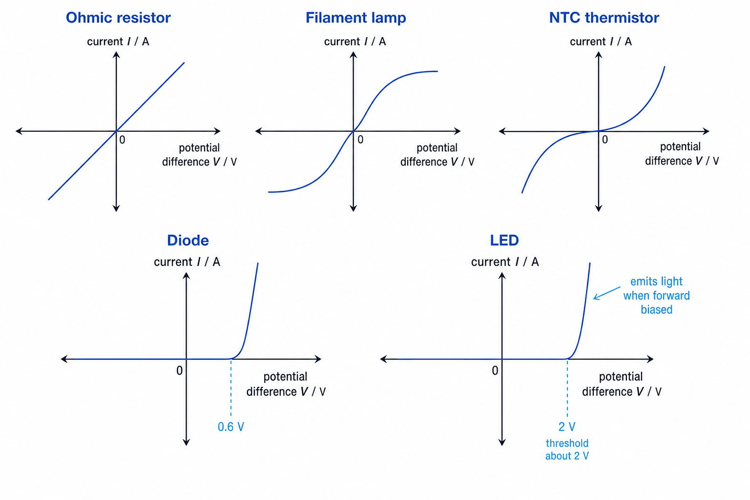
For a straight-line I–V graph:
ΔIΔV=1R\frac{\Delta I}{\Delta V} = \frac{1}{R}ΔVΔI=R1So on an I–V graph, a steeper line means a lower resistance. For a curved graph, the changing slope shows that the resistance is changing.
Using the wrong gradient
If current is on the vertical axis and potential difference is on the horizontal axis, the gradient is I/VI/VI/V, not V/IV/IV/I. For an ohmic component, resistance is the reciprocal of the gradient.
Ohmic resistor
An ohmic resistor has a straight-line I–V graph through the origin. The same pattern appears for positive and negative potential differences: reversing the potential difference reverses the current.
Filament lamp
A filament lamp is non-ohmic. As current increases, the metal filament gets hotter. At higher temperature, metal ions vibrate more, so electrons collide more often and the resistance increases.
Its I–V graph curves so that it becomes less steep at larger positive and negative potential differences.
NTC thermistor
A thermistor is a resistor whose resistance depends strongly on temperature. An NTC thermistor has a negative temperature coefficient, meaning its resistance decreases as temperature increases.
As current through an NTC thermistor increases, it may heat up. This reduces its resistance, so the I–V graph becomes steeper at larger potential differences.
Diode and LED
A diode allows current mainly in one direction. Forward bias means the potential difference is applied in the conducting direction; reverse bias means the opposite polarity is applied.
A silicon diode has very little current until about 0.6 V in forward bias, then the current rises rapidly.
An LED, or light-emitting diode, behaves like a diode but emits light when forward biased. Its threshold potential difference is typically larger, often around 2 V, depending on the LED. LEDs must normally be used with a series resistor to limit the current.
Comparing resistance in a filament lamp
A filament lamp has a current of 0.40 A at 2.0 V, and a current of 0.60 A at 6.0 V. Show how its resistance changes.
-
Calculate the resistance at the lower potential difference:
R=2.0 V0.40 A=5.0 ΩR = \frac{2.0\ \text{V}}{0.40\ \text{A}} = 5.0\ \OmegaR=0.40 A2.0 V=5.0 Ω -
Calculate the resistance at the higher potential difference:
R=6.0 V0.60 A=10 ΩR = \frac{6.0\ \text{V}}{0.60\ \text{A}} = 10\ \OmegaR=0.60 A6.0 V=10 Ω -
Compare the values. The resistance has doubled because the filament is hotter at the higher current, so the lamp is non-ohmic.
Investigating I–V characteristics
To investigate a component, you need to measure the current through it and the potential difference across it. An ammeter measures current and is connected in series. A voltmeter measures potential difference and is connected in parallel across the component.
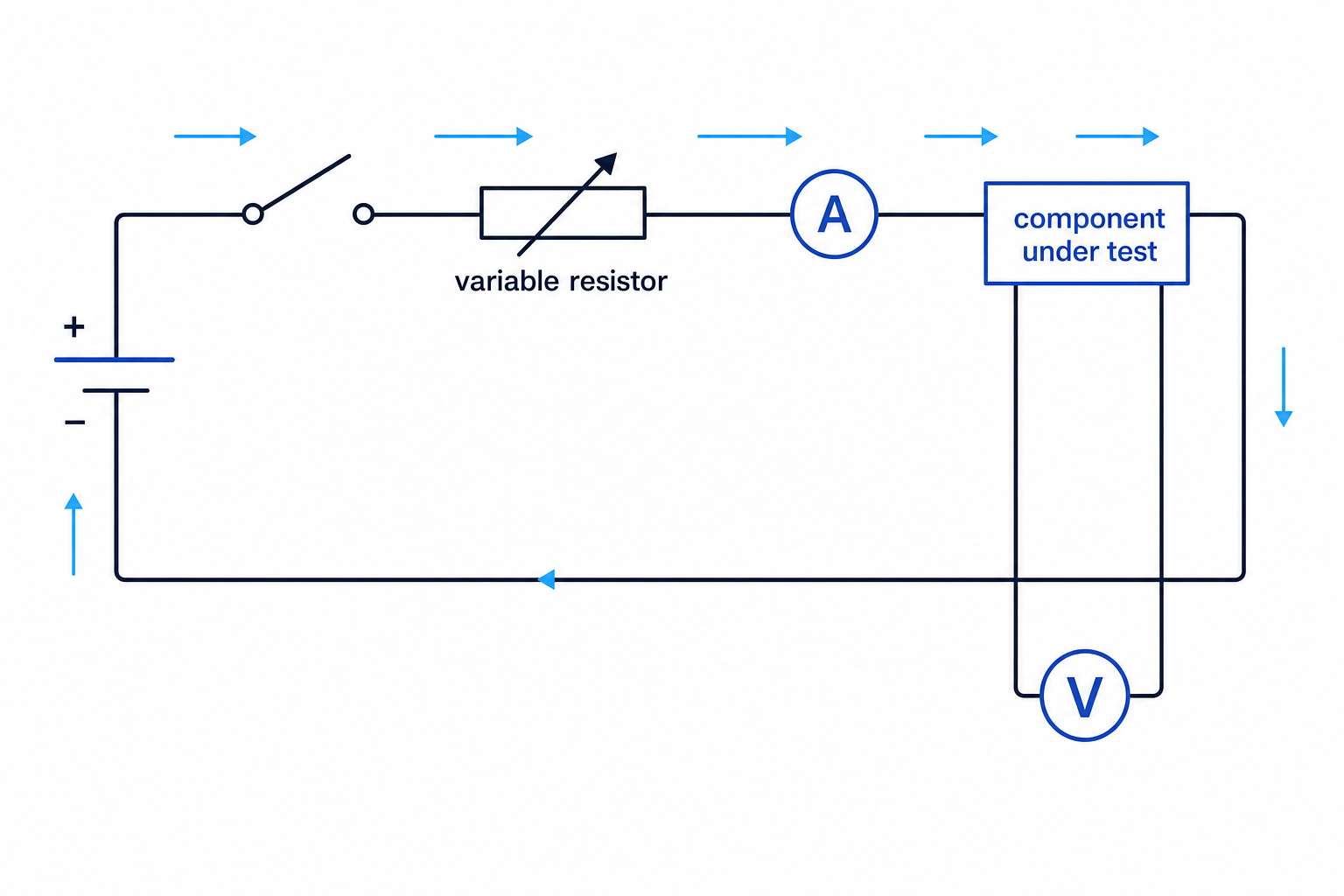
A good procedure is:
- Connect the component under test with an ammeter in series and a voltmeter in parallel across the component.
- Use a variable resistor or variable power supply to change the potential difference in small steps.
- Record pairs of readings of VVV and III once the readings are steady.
- Reverse the supply connections to obtain negative values of VVV and III, if it is safe for the component.
- Plot an I–V scatter graph using a spreadsheet, then add a suitable best-fit line or curve.
For diodes and LEDs, include a protective series resistor and do not exceed the current rating. For filament lamps, heating is part of the behaviour, so allow readings to settle. For thermistors, decide whether you are controlling temperature or allowing self-heating.
Measure the same component
The voltmeter must be across the same component whose current is measured by the ammeter. Otherwise, the ratio V/IV/IV/I will not give the resistance of that component.
Finding resistance from a straight I–V graph
A spreadsheet graph for a resistor gives a straight best-fit line through the origin. The line passes through 5.0 V and 0.20 A. Find the resistance.
-
Calculate the graph gradient using current divided by potential difference:
ΔIΔV=0.20 A5.0 V=0.040 A V−1\frac{\Delta I}{\Delta V} = \frac{0.20\ \text{A}}{5.0\ \text{V}} = 0.040\ \text{A}\,\text{V}^{-1}ΔVΔI=5.0 V0.20 A=0.040 AV−1 -
For an I–V graph of an ohmic resistor, use the reciprocal relationship:
R=10.040 A V−1=25 ΩR = \frac{1}{0.040\ \text{A}\,\text{V}^{-1}} = 25\ \OmegaR=0.040 AV−11=25 Ω -
Because the graph is a straight line through the origin, the resistor is ohmic over the measured range.
Light-dependent resistors
A light-dependent resistor, or LDR, is a component whose resistance changes with light intensity.
LDR
An LDR has a high resistance in the dark and a much lower resistance in bright light.
As light intensity increases, more charge carriers are available in the semiconductor material, so the resistance decreases. You do not need a precise equation for this variation; you should know the qualitative trend.
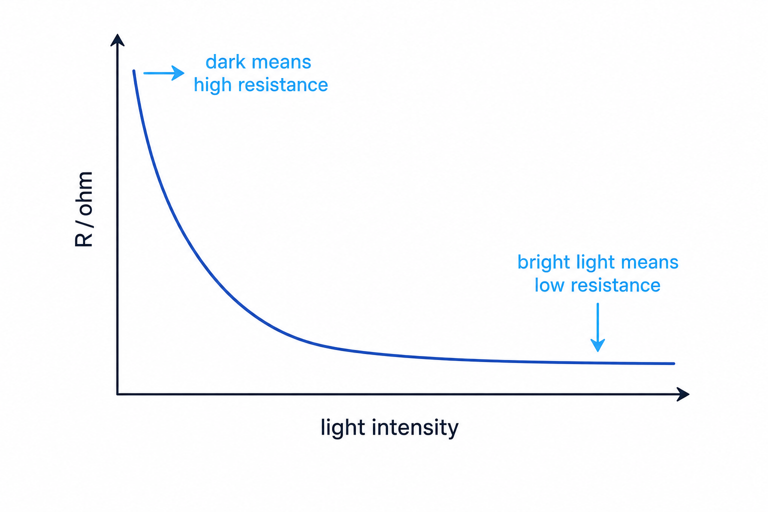
Comparing LDR resistance in dark and bright conditions
An LDR has 3.0 V across it. In the dark, the current is 0.15 mA. In bright light, the current is 2.0 mA. Compare the resistances.
-
Calculate the dark resistance:
R=3.0 V0.15×10−3 A=2.0×10⁴ Ω=20 kΩR = \frac{3.0\ \text{V}}{0.15 \times 10^{-3}\ \text{A}} = 2.0 \times 10^{4}\ \Omega = 20\ \text{k}\OmegaR=0.15×10⁻³ A3.0 V=2.0×10⁴ Ω=20 kΩ -
Calculate the bright-light resistance:
R=3.0 V2.0×10−3 A=1.5×10³ Ω=1.5 kΩR = \frac{3.0\ \text{V}}{2.0 \times 10^{-3}\ \text{A}} = 1.5 \times 10^{3}\ \Omega = 1.5\ \text{k}\OmegaR=2.0×10⁻³ A3.0 V=1.5×10³ Ω=1.5 kΩ -
Compare the values. The resistance is much lower in bright light, as expected for an LDR.
In the exam
- Always check the graph axes before using a gradient: on an I–V graph, gradient is I/VI/VI/V, so resistance is the reciprocal for a straight ohmic line.
- When stating Ohm’s law, include the condition “constant temperature”.
- For non-ohmic components, calculate R=V/IR = V/IR=V/I at the specific operating point and explain the change using heating, temperature or semiconductor behaviour.
- In practical questions, put the ammeter in series and the voltmeter in parallel across the component under test.
Check yourself
- Why does the I–V graph for a filament lamp become less steep at higher potential differences?
- If an I–V graph has a gradient of 0.20 A V−10.20\ \text{A}\,\text{V}^{-1}0.20 AV−1, what is the resistance?
- How does the resistance of an LDR change when it moves from darkness into bright light?
