

What you'll learn
- What magnetic fields are and why they come from moving charges or permanent magnets.
- How to sketch and interpret magnetic field lines for wires, coils and solenoids.
- How to use Fleming’s left-hand rule to find the direction of a magnetic force.
- How to apply F=BILsinθF = BIL\sin\thetaF=BILsinθ and measure magnetic flux density using a digital balance.
1. Where magnetic fields come from
A magnetic field is not a substance — it is a region of space where magnetic forces can act. You meet magnetic fields around permanent magnets, but also around any moving charge. In a metal wire, an electric current is made from moving charges, so a current-carrying wire produces a magnetic field.
Magnetic field
A magnetic field is a region in which a moving charge, a current-carrying conductor, or a permanent magnet can experience a magnetic force.
A permanent magnet has a magnetic field because many tiny magnetic regions inside it are aligned. You do not need a detailed atomic model here — just remember that permanent magnets and moving charges both produce magnetic fields.
The source of magnetic fields
Magnetic fields are produced by moving charges and by permanent magnets. A current in a wire is moving charge, so it creates a magnetic field around the wire.
2. Magnetic field lines
We use magnetic field lines to map magnetic fields. They are a model: you cannot see physical lines in space, but the diagram tells you useful information.
Magnetic field lines
A magnetic field line is a line drawn so that its tangent gives the direction of the magnetic field at that point. Closer spacing means a stronger field.
The direction of a magnetic field is the direction a north magnetic pole would move. Outside a permanent magnet, field lines go from north to south. Field lines never cross, because the field cannot have two directions at one point.
A uniform magnetic field has the same magnitude and direction throughout a region. On a diagram, this is shown by straight, parallel, equally spaced field lines.
3. Field patterns you must recognise
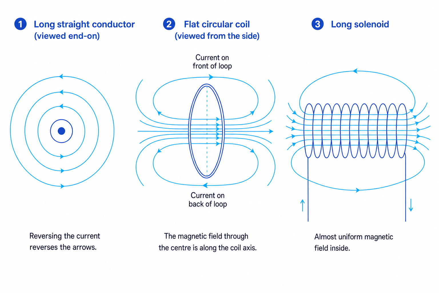
For OCR A, you need the field patterns for a long straight current-carrying conductor, a flat coil and a long solenoid.
Long straight current-carrying conductor
A current in a long straight wire produces circular magnetic field lines centred on the wire.
Use the right-hand grip rule:
- Point your right thumb in the direction of conventional current.
- Your curled fingers show the direction of the magnetic field lines.
Flat coil
A flat coil is a loop of wire. Its field pattern is like a short bar magnet: field lines pass through the centre along the axis of the coil and curve around outside.
If you look at one face of the coil:
- anticlockwise current means that face acts like a north pole;
- clockwise current means that face acts like a south pole.
Long solenoid
A solenoid is a coil with many turns, usually shaped like a long cylinder. Inside a long solenoid, the field is almost uniform: the field lines are nearly parallel and evenly spaced. Outside, the field is weaker and more spread out.
Dots and crosses
A dot means a vector is coming out of the page, like the tip of an arrow. A cross means it is going into the page, like the tail of an arrow.
Using the right-hand grip rule
A vertical wire carries conventional current upwards. Find the direction of the magnetic field on the right-hand side of the wire.
- Point your right thumb upwards, because the thumb follows the conventional current.
- Curl your fingers around the wire; on the right-hand side, your fingers point into the page.
- Therefore, the magnetic field at that point is into the page.
4. Fleming’s left-hand rule and the motor effect
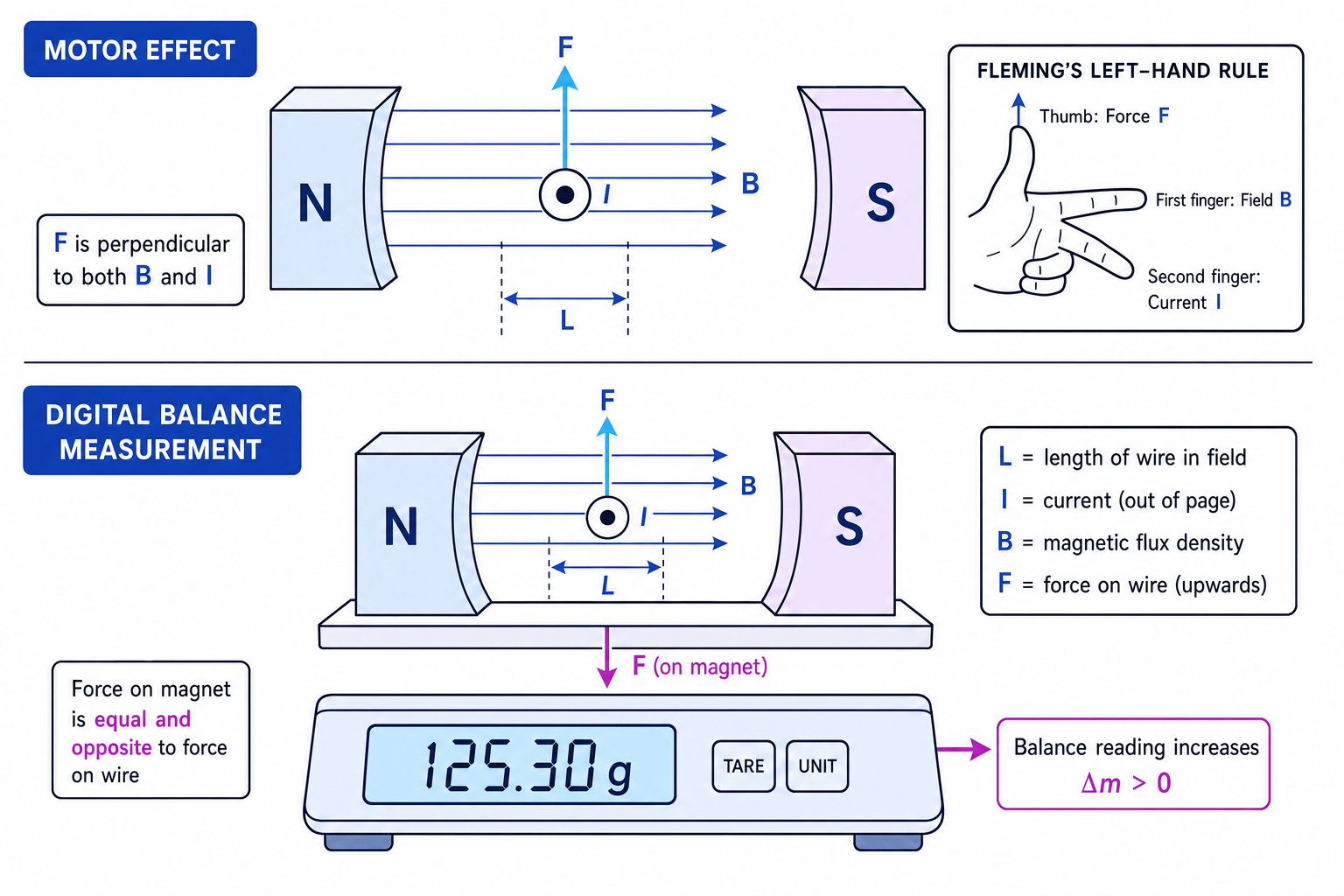
A current-carrying wire in a magnetic field can experience a force. This is called the motor effect. The force is perpendicular to both the current and the magnetic field.
To find the direction, use Fleming’s left-hand rule:
- First finger: magnetic field, from north to south.
- Second finger: conventional current.
- Thumb: force or motion.
Your thumb, first finger and second finger must all be at right angles to each other.
Using electron flow instead of conventional current
Fleming’s left-hand rule uses conventional current, from positive to negative. In a metal wire, electrons move the opposite way, but you should still use conventional current unless the question explicitly discusses electron motion.
Finding the direction of the force
A wire carries conventional current out of the page between a north pole on the left and a south pole on the right.
- The magnetic field is from north to south, so BBB is to the right.
- Put your left-hand first finger to the right and your second finger out of the page.
- Your thumb points upwards, so the force on the wire is upwards. The magnet experiences an equal and opposite downward force.
5. Force on a current-carrying conductor
The size of the force on a straight current-carrying conductor in a uniform magnetic field is
F=BILsinθF = BIL\sin\thetaF=BILsinθwhere:
- FFF is the force on the conductor in newtons, N;
- BBB is the magnetic flux density in tesla, T;
- III is the current in amperes, A;
- LLL is the length of wire inside the magnetic field in metres, m;
- θ\thetaθ is the angle between the current direction and the magnetic field.
If the wire is perpendicular to the field, θ=90∘\theta = 90^\circθ=90∘, so sin90∘=1\sin 90^\circ = 1sin90∘=1 and
F=BILF = BILF=BILIf the wire is parallel to the field, θ=0∘\theta = 0^\circθ=0∘, so there is no force.
Magnetic flux density
Magnetic flux density, symbol BBB, is defined by the force per unit current per unit length on a conductor placed at right angles to a uniform magnetic field.
One tesla is the magnetic flux density that gives a force of one newton on a one metre length of wire carrying a current of one ampere at right angles to the field:
1 T=1 N A−1 m−11\,\text{T} = 1\,\text{N}\,\text{A}^{-1}\,\text{m}^{-1}1T=1NA−1m−1Calculating the force on a wire
A wire of length 6.0 cm is in a uniform magnetic field of flux density 0.42 T. It carries a current of 4.0 A at an angle of 30° to the field. Calculate the force on the wire.
-
Convert the length to metres: L=6.0 cm=0.060 mL = 6.0\,\text{cm} = 0.060\,\text{m}L=6.0cm=0.060m.
-
Substitute into F=BILsinθF = BIL\sin\thetaF=BILsinθ:
F=(0.42 T)(4.0 A)(0.060 m)sin30∘F = (0.42\,\text{T})(4.0\,\text{A})(0.060\,\text{m})\sin 30^\circF=(0.42T)(4.0A)(0.060m)sin30∘ -
Calculate the force:
F=5.04×10⁻² NF = 5.04 \times 10^{-2}\,\text{N}F=5.04×10⁻²NSo the force is 5.0×10⁻² N5.0 \times 10^{-2}\,\text{N}5.0×10⁻²N to two significant figures.
Forgetting the angle
Do not automatically use F=BILF = BILF=BIL. That only works when the current is perpendicular to the field. If the angle is given, use F=BILsinθF = BIL\sin\thetaF=BILsinθ.
6. Measuring magnetic flux density with a digital balance
You can determine the uniform magnetic flux density between magnet poles using a current-carrying wire and a digital balance.
Apparatus and method
Place the magnet on a digital balance and hold a straight wire between the pole pieces, without touching the magnet. The wire should be perpendicular to the magnetic field, so θ=90∘\theta = 90^\circθ=90∘.
When current flows, the wire experiences a force. By Newton’s third law, the magnet experiences an equal and opposite force. This changes the balance reading.
A good method is:
- Measure the length LLL of wire actually inside the uniform field region.
- Tare the balance with no current.
- Set a current III and record the change in balance reading.
- Repeat for several currents, including reversed current if useful.
- Convert the balance reading change into force using F=ΔmgF = \Delta mgF=Δmg.
- Plot force FFF against current III. Since F=BILF = BILF=BIL, the gradient is BLBLBL, so BBB is gradient divided by LLL.
If you plot mass change Δm\Delta mΔm against current III instead, then
Δm=BLgI\Delta m = \frac{BL}{g}IΔm=gBLIso
B=g×gradientLB = \frac{g \times \text{gradient}}{L}B=Lg×gradientPractical sanity checks
Use kilograms for balance readings in calculations, not grams. Keep the wire centred between the poles, switch off between readings to reduce heating, and measure only the length of wire inside the field.
Determining magnetic flux density from a balance graph
A wire of length 4.0 cm is perpendicular to the uniform field between two magnet poles. A graph of mass change Δm\Delta mΔm against current III has gradient 1.85×10⁻⁴ kg A−11.85 \times 10^{-4}\,\text{kg A}^{-1}1.85×10⁻⁴kg A−1. Calculate BBB.
-
Convert the wire length to metres: L=4.0 cm=0.040 mL = 4.0\,\text{cm} = 0.040\,\text{m}L=4.0cm=0.040m.
-
Use the relationship for a mass-change graph:
B=g×gradientLB = \frac{g \times \text{gradient}}{L}B=Lg×gradient -
Substitute the values:
B=(9.81 m s−2)(1.85×10⁻⁴ kg A−1)0.040 mB = \frac{(9.81\,\text{m s}^{-2})(1.85 \times 10^{-4}\,\text{kg A}^{-1})}{0.040\,\text{m}}B=0.040m(9.81m s−2)(1.85×10⁻⁴kg A−1) -
Calculate and give a sensible answer:
B=4.5×10−2 TB = 4.5 \times 10^{-2}\,\text{T}B=4.5×10⁻²T
Using the whole wire length
In F=BILsinθF = BIL\sin\thetaF=BILsinθ, LLL is only the length of wire within the magnetic field. Do not use the total length of wire connected in the circuit.
In the exam
- For directions, decide the field direction first, then the conventional current direction, then apply Fleming’s left-hand rule.
- For calculations, check whether the wire is perpendicular to the field. If not, use F=BILsinθF = BIL\sin\thetaF=BILsinθ.
- In balance experiments, convert the balance change to a force using F=ΔmgF = \Delta mgF=Δmg, and convert grams to kilograms before substituting.
Check yourself
- What is the difference between the magnetic field pattern around a straight wire and inside a long solenoid?
- A wire is parallel to a magnetic field. What force acts on it, and why?
- In the digital balance method, why does the balance reading change when the current is switched on?
