

What you'll learn
- How to calculate magnetic flux and magnetic flux linkage.
- How Faraday’s law and Lenz’s law predict induced e.m.f.s and their directions.
- How search coils can measure magnetic flux density.
- How simple a.c. generators and transformers use changing flux linkage.
Starting point: magnetic field lines and coil orientation
A magnetic field can be represented by field lines. The closer together the lines, the stronger the field. The quantity used for field strength is magnetic flux density, symbol BBB, measured in tesla (T).
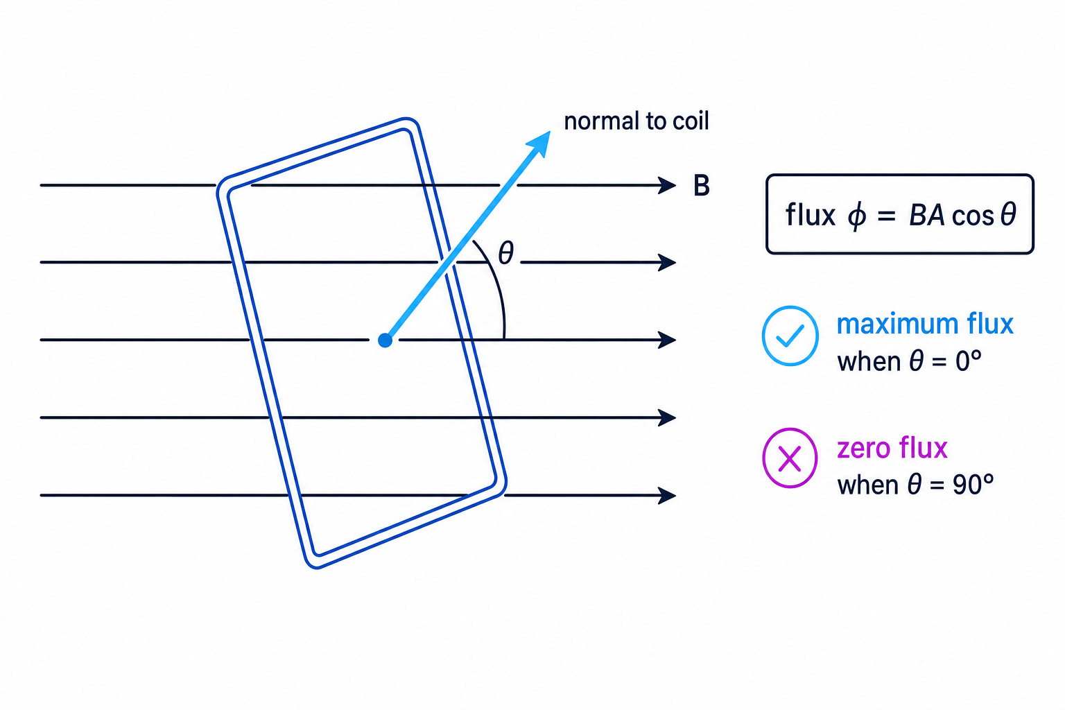
When a coil is placed in a magnetic field, its orientation matters. We describe the orientation using the normal: an imaginary line at right angles to the plane of the coil.
The angle θ\thetaθ in the flux equation is the angle between the magnetic field direction and the normal to the coil.
Magnetic flux
Magnetic flux
Magnetic flux, symbol ϕ\phiϕ, measures how much magnetic field passes through an area. For a uniform magnetic field through a flat area,
ϕ=BAcosθ\phi = BA\cos\thetaϕ=BAcosθwhere BBB is magnetic flux density in tesla (T), AAA is area in square metres (m²), and θ\thetaθ is the angle between BBB and the normal to the area.
The unit of magnetic flux is the weber (Wb).
1 Wb=1 T m21\ \text{Wb} = 1\ \text{T m}^21 Wb=1 T m2Flux is maximum when the normal to the coil is parallel to the field, so θ=0∘\theta = 0^\circθ=0∘ and cosθ=1\cos\theta = 1cosθ=1.
Flux is zero when the normal to the coil is perpendicular to the field, so θ=90∘\theta = 90^\circθ=90∘ and cosθ=0\cos\theta = 0cosθ=0.
Using the wrong angle
In ϕ=BAcosθ\phi = BA\cos\thetaϕ=BAcosθ, θ\thetaθ is measured from the normal, not from the plane of the coil. If you are given the angle between the field and the plane, you must convert it first.
Magnetic flux linkage
A coil usually has many turns. If each turn links the same magnetic flux, the total linked flux is larger.
Magnetic flux linkage
Magnetic flux linkage is the product of the number of turns NNN and the magnetic flux through each turn:
NϕN\phiNϕFor a uniform field and identical turns,
Nϕ=NBAcosθN\phi = NBA\cos\thetaNϕ=NBAcosθFlux linkage is often quoted in weber turns. Since “turns” is just a count, it is dimensionally equivalent to webers.
Calculating flux linkage
A coil has 80 turns and area 4.0×10⁻³ m24.0 \times 10^{-3}\ \text{m}^24.0×10⁻³ m2. It is placed in a uniform magnetic field of flux density 0.18 T0.18\ \text{T}0.18 T. The normal to the coil is at 60∘60^\circ60∘ to the field. Calculate the magnetic flux linkage.
-
Calculate the flux through one turn using the angle between the field and the normal:
ϕ=BAcosθ\phi = BA\cos\thetaϕ=BAcosθ ϕ=0.18×4.0×10−3×cos60∘\phi = 0.18 \times 4.0 \times 10^{-3} \times \cos 60^\circϕ=0.18×4.0×10−3×cos60∘ -
Evaluate the flux per turn:
ϕ=3.6×10⁻⁴ Wb\phi = 3.6 \times 10^{-4}\ \text{Wb}ϕ=3.6×10⁻⁴ Wb -
Multiply by the number of turns:
Nϕ=80×3.6×10−4N\phi = 80 \times 3.6 \times 10^{-4}Nϕ=80×3.6×10−4 Nϕ=2.9×10⁻² Wb turnsN\phi = 2.9 \times 10^{-2}\ \text{Wb turns}Nϕ=2.9×10⁻² Wb turns
Electromagnetic induction
Electromagnetic induction is the production of an e.m.f. when magnetic flux linkage changes.
Induced e.m.f.
An induced e.m.f. is a voltage produced by a changing magnetic flux linkage. It can produce a current if the circuit is complete.
You can change flux linkage by changing:
- the magnetic flux density BBB
- the area AAA inside the field
- the angle θ\thetaθ
- the number of turns linked by the flux, NNN
In most A-Level examples, the number of turns is fixed, and the flux changes because the coil moves, rotates, or the magnetic field changes.
Faraday’s law
Faraday’s law
The magnitude of the induced e.m.f. depends on the rate of change of magnetic flux linkage. A faster change produces a larger induced e.m.f.
OCR gives this as:
E=−Δ(Nϕ)ΔtE = -\frac{\Delta(N\phi)}{\Delta t}E=−ΔtΔ(Nϕ)where EEE is induced e.m.f. in volts (V), Δ(Nϕ)\Delta(N\phi)Δ(Nϕ) is the change in magnetic flux linkage, and Δt\Delta tΔt is the time interval in seconds (s).
This equation gives the average induced e.m.f. over the time interval. On a graph of flux linkage against time, the induced e.m.f. is linked to the gradient.
Since volt seconds are equivalent to webers,
1 V s=1 Wb1\ \text{V s} = 1\ \text{Wb}1 V s=1 WbLenz’s law
Lenz’s law
Lenz’s law states that the direction of the induced e.m.f. is such that it opposes the change that produced it.
The minus sign in Faraday’s law represents Lenz’s law. It is not just a “negative answer”; it tells you about direction.
This opposition is essential for conservation of energy. If the induced current helped the change that caused it, energy would appear from nowhere.
Using Faraday’s law and Lenz’s law
The magnetic flux through each turn of a 150-turn coil decreases from 2.0×10⁻⁴ Wb2.0 \times 10^{-4}\ \text{Wb}2.0×10⁻⁴ Wb into the page to 0.50×10⁻⁴ Wb0.50 \times 10^{-4}\ \text{Wb}0.50×10⁻⁴ Wb into the page in 0.020 s0.020\ \text{s}0.020 s. Calculate the average induced e.m.f. and state the direction of the induced current.
-
Calculate the change in flux linkage:
Δ(Nϕ)=N(ϕf−ϕi)\Delta(N\phi) = N(\phi_f - \phi_i)Δ(Nϕ)=N(ϕf−ϕi) Δ(Nϕ)=150(0.50×10⁻⁴−2.0×10⁻⁴)\Delta(N\phi) = 150(0.50 \times 10^{-4} - 2.0 \times 10^{-4})Δ(Nϕ)=150(0.50×10⁻⁴−2.0×10⁻⁴) Δ(Nϕ)=−2.25×10⁻² Wb turns\Delta(N\phi) = -2.25 \times 10^{-2}\ \text{Wb turns}Δ(Nϕ)=−2.25×10⁻² Wb turns -
Apply Faraday’s law:
E=−Δ(Nϕ)ΔtE = -\frac{\Delta(N\phi)}{\Delta t}E=−ΔtΔ(Nϕ) E=−−2.25×10−20.020E = -\frac{-2.25 \times 10^{-2}}{0.020}E=−0.020−2.25×10⁻² E=1.1 VE = 1.1\ \text{V}E=1.1 V -
Apply Lenz’s law. The flux into the page is decreasing, so the induced current must create a magnetic field into the page. For a loop viewed on the page, that requires a clockwise current.
Investigating magnetic flux using a search coil
A search coil is a small coil with a known number of turns and known area. It is connected to an oscilloscope, data logger, or sensitive voltmeter.
To investigate magnetic flux density:
- Place the search coil in the magnetic field with its normal parallel to the field.
- Quickly remove it from the field, or rotate it through a known angle.
- Record the induced e.m.f. pulse against time.
- Find the area under the e.m.f.–time graph.
From Faraday’s law, the area under the e.m.f.–time graph gives the change in flux linkage:
area under E-t graph=Δ(Nϕ)\text{area under } E\text{-}t\text{ graph} = \Delta(N\phi)area under E-t graph=Δ(Nϕ)For magnitudes, you can ignore the sign and use the size of the area.
Finding magnetic flux density with a search coil
A search coil has 500 turns and area 1.6×10⁻⁴ m21.6 \times 10^{-4}\ \text{m}^21.6×10⁻⁴ m2. It is pulled completely out of a uniform magnetic field. The area under the induced e.m.f.–time graph is 4.8×10⁻³ V s4.8 \times 10^{-3}\ \text{V s}4.8×10⁻³ V s. Calculate the magnetic flux density.
-
Convert the graph area into a change in flux linkage:
∣Δ(Nϕ)∣=4.8×10⁻³ Wb turns|\Delta(N\phi)| = 4.8 \times 10^{-3}\ \text{Wb turns}∣Δ(Nϕ)∣=4.8×10⁻³ Wb turns -
Since the coil starts with its normal parallel to the field and ends outside the field:
∣Δ(Nϕ)∣=NBA|\Delta(N\phi)| = NBA∣Δ(Nϕ)∣=NBA -
Rearrange and substitute:
B=∣Δ(Nϕ)∣NAB = \frac{|\Delta(N\phi)|}{NA}B=NA∣Δ(Nϕ)∣ B=4.8×10−3500×1.6×10−4B = \frac{4.8 \times 10^{-3}}{500 \times 1.6 \times 10^{-4}}B=500×1.6×10−44.8×10−3 B=6.0×10−2 TB = 6.0 \times 10^{-2}\ \text{T}B=6.0×10⁻² T
Search-coil sanity check
For the same total change in flux linkage, moving the coil faster gives a taller, narrower e.m.f. pulse. The area under the graph should be roughly unchanged.
Rotation through 180 degrees
If a search coil is rotated through 180°, the flux linkage changes from +NBA+NBA+NBA to −NBA-NBA−NBA. The magnitude of the change is therefore 2NBA2NBA2NBA, not NBANBANBA.
Simple a.c. generator
A simple a.c. generator has a coil rotating in a magnetic field. As the coil rotates, the angle θ\thetaθ changes continuously, so the magnetic flux linkage changes continuously. By Faraday’s law, this produces an induced e.m.f.
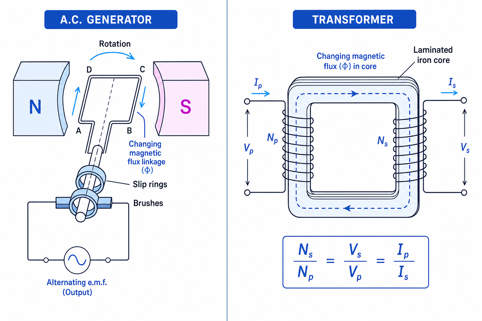
The output is alternating because the direction of the induced e.m.f. reverses every half-turn.
The generator uses:
- a rotating coil
- a magnetic field, often between two poles
- slip rings, which rotate with the coil
- brushes, which maintain electrical contact with the external circuit
When the flux linkage is changing fastest, the induced e.m.f. is largest. When the flux linkage is momentarily at a maximum or minimum, its rate of change is zero, so the induced e.m.f. is zero.
Linking generator position to induced e.m.f.
A generator coil rotates at constant speed. At one instant, the plane of the coil is perpendicular to the magnetic field. Decide whether the induced e.m.f. is maximum or zero.
-
If the plane of the coil is perpendicular to the field, the normal to the coil is parallel to the field, so the flux linkage is maximum.
-
At a maximum value on a flux-linkage–time graph, the gradient is zero.
-
Since induced e.m.f. depends on the rate of change of flux linkage, the induced e.m.f. is zero at that instant.
Increasing generator output
A larger peak e.m.f. can be produced by increasing the magnetic flux density, increasing the coil area, increasing the number of turns, or rotating the coil faster.
Transformers
A transformer changes the size of an alternating voltage. It works using electromagnetic induction.
Transformer
A transformer consists of a primary coil and a secondary coil wound around a laminated iron core. An alternating current in the primary coil produces a changing magnetic flux in the core, which induces an e.m.f. in the secondary coil.
The primary coil is connected to the input supply. The secondary coil is connected to the output circuit.
The iron core helps the changing magnetic flux link both coils. The core is laminated, meaning it is made from thin insulated sheets. This reduces eddy currents, which are unwanted circulating currents induced in the core that waste energy as heating.
Expecting a transformer to work on steady d.c.
A transformer needs a changing magnetic flux. A steady direct current produces no continuous change in flux, so it gives no continuous secondary e.m.f. It may also cause overheating in the primary coil.
The ideal transformer equation
For an ideal transformer, there are no energy losses and all the magnetic flux produced by the primary links the secondary.
OCR gives:
NsNp=VsVp=IpIs\frac{N_s}{N_p} = \frac{V_s}{V_p} = \frac{I_p}{I_s}NpNs=VpVs=IsIpwhere:
- NpN_pNp and NsN_sNs are the numbers of turns on the primary and secondary coils
- VpV_pVp and VsV_sVs are the primary and secondary voltages
- IpI_pIp and IsI_sIs are the primary and secondary currents
A step-up transformer has more secondary turns than primary turns, so it increases voltage and decreases current.
A step-down transformer has fewer secondary turns than primary turns, so it decreases voltage and increases current.
Calculating transformer voltage and current
An ideal transformer has 200 turns on the primary coil and 800 turns on the secondary coil. The primary voltage is 6.0 V6.0\ \text{V}6.0 V and the primary current is 0.50 A0.50\ \text{A}0.50 A. Calculate the secondary voltage and current.
-
Calculate the turns ratio:
NsNp=800200=4.0\frac{N_s}{N_p} = \frac{800}{200} = 4.0NpNs=200800=4.0 -
Use the voltage ratio:
VsVp=4.0\frac{V_s}{V_p} = 4.0VpVs=4.0 Vs=4.0×6.0=24 VV_s = 4.0 \times 6.0 = 24\ \text{V}Vs=4.0×6.0=24 V -
Use the current ratio:
IpIs=4.0\frac{I_p}{I_s} = 4.0IsIp=4.0 Is=0.504.0=0.125 AI_s = \frac{0.50}{4.0} = 0.125\ \text{A}Is=4.00.50=0.125 A -
Check using power conservation for an ideal transformer:
VpIp=6.0×0.50=3.0 WV_p I_p = 6.0 \times 0.50 = 3.0\ \text{W}VpIp=6.0×0.50=3.0 W VsIs=24×0.125=3.0 WV_s I_s = 24 \times 0.125 = 3.0\ \text{W}VsIs=24×0.125=3.0 W
Investigating transformers practically
To investigate transformers, you can use two coils on a laminated iron core and a low-voltage a.c. supply.
A good procedure is:
- Keep the primary voltage and frequency constant.
- Vary the number of turns on the secondary coil.
- Measure the secondary voltage using an a.c. voltmeter.
- Plot secondary voltage against number of secondary turns.
For an ideal transformer, VsV_sVs should be directly proportional to NsN_sNs when NpN_pNp and VpV_pVp are fixed.
If you investigate currents, connect a load resistor to the secondary circuit and use ammeters in series. Real transformers will not be perfectly ideal because of coil resistance, flux leakage, core heating and eddy current losses.
Practical measurements
Use low voltages, switch off between readings if the coils warm up, and compare repeated readings. Deviations from the ideal equation are usually evidence of energy losses or incomplete flux linkage.
In the exam
-
Always decide whether the question is about flux, flux linkage, or rate of change of flux linkage before choosing an equation.
-
For ϕ=BAcosθ\phi = BA\cos\thetaϕ=BAcosθ, check that θ\thetaθ is measured from the normal to the coil, not from the plane of the coil.
-
Use Lenz’s law for direction questions: the induced current opposes the change, not necessarily the original field.
-
For transformers, remember that stepping up voltage steps down current in the ideal case.
Check yourself
- Why is the induced e.m.f. zero when the flux linkage is maximum in a rotating generator coil?
- A search coil is rotated through 180° instead of removed from the field. How does that change the flux-linkage calculation?
- Why must a transformer use an alternating current rather than a steady direct current?
