What you'll learn
- Recognise the standard circuit symbols used in OCR A-Level Physics A.
- Understand how wires, junctions, switches, sources, components, and meters are represented.
- Draw and interpret circuit diagrams without confusing the physical layout with the electrical connections.
- Place ammeters and voltmeters correctly in a circuit diagram.
Why circuit symbols matter
Real electrical circuits can look messy: wires loop around, components are different sizes, and the physical layout may not show clearly how the circuit works. A circuit diagram removes that clutter. It uses agreed symbols to show the electrical connections.
Circuit symbol
A circuit symbol is a standard simplified drawing used to represent an electrical component, such as a cell, resistor, lamp, switch, ammeter, or voltmeter.
OCR points you towards the standard UK school and A-Level symbols used in the ASE guidance. The point is not artistic drawing: it is communication. Another physicist should be able to read your circuit diagram and build the same circuit.
Symbols are a shared language
A circuit diagram shows which points are connected to which, not what the circuit physically looks like on the bench.
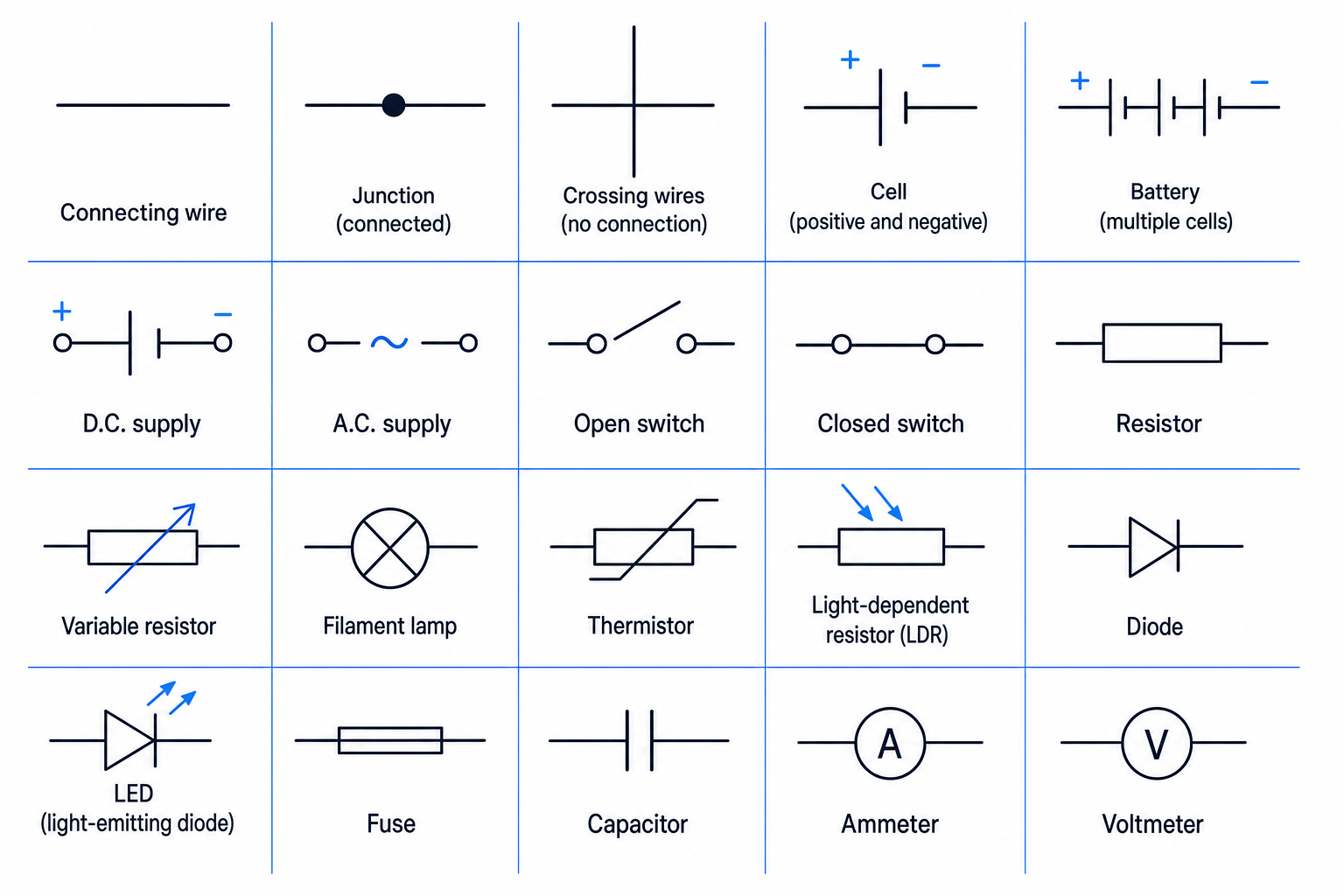
The chart below is a useful visual reference for the main symbols you are expected to recognise and use.

Power sources
A cell supplies electrical energy to charges in a circuit. In the cell symbol, the longer line is the positive terminal and the shorter line is the negative terminal.
A battery is two or more cells connected together. In everyday speech people often say “battery” for a single cell, but in circuit-symbol language it is useful to keep the distinction clear.
A d.c. supply provides a potential difference with fixed polarity. D.C. stands for direct current, meaning the current is in one direction around the circuit.
An a.c. supply provides a potential difference that reverses direction periodically. A.C. stands for alternating current.
Conventional current
Conventional current is the direction in which positive charge would flow. In a simple d.c. circuit, conventional current leaves the positive terminal of the cell or supply and returns to the negative terminal.
You do not always need to draw current arrows, but if you do, use conventional current unless the question specifically asks about electrons.
Wires, junctions and switches
A connecting wire is drawn as a straight line. In ideal circuit diagrams, wires are treated as having negligible resistance unless the question says otherwise.
A junction is a point where wires are electrically connected, so current can split or join. Junctions are often marked with a filled dot.
A pair of wires crossing without a dot usually means they are not connected. This matters a lot: a dot can change the entire circuit.
Confusing crossings with junctions
Do not assume every crossing means a connection. A filled dot means connected; a plain crossing usually means the wires simply pass over one another.
A switch controls whether a circuit path is complete. An open switch breaks the circuit, so there is no complete conducting path through that branch. A closed switch completes the path.
Components that affect or use electrical energy
A resistor is a component that opposes current. In circuit diagrams for UK A-Level Physics, it is usually drawn as a rectangle.
A variable resistor has a resistance that can be adjusted. It is shown as a resistor with an arrow through it.
A filament lamp transfers electrical energy mainly to thermal energy and light. It is drawn as a circle with a cross inside.
A thermistor is a resistor whose resistance depends on temperature. In typical school circuits, its resistance decreases as temperature increases, unless stated otherwise.
A light-dependent resistor, or LDR, is a resistor whose resistance depends on light intensity. Its resistance decreases when light intensity increases.
A diode allows current much more easily in one direction than the other. A light-emitting diode, or LED, is a diode that emits light when current flows through it in the forward direction.
A fuse is a safety component designed to melt and break the circuit if the current becomes too large.
A capacitor stores charge and energy in an electric field. You meet capacitor behaviour in more detail later, but you should still recognise the symbol.
Arrows on light components
- On an LDR, arrows point towards the resistor: light is arriving.
- On an LED, arrows point away from the diode: light is being emitted.
Measuring instruments
An ammeter measures current. Current is the rate of flow of charge and is measured in amperes, A. To measure the current through a component, the ammeter must be in the same branch as that component.
A voltmeter measures potential difference. Potential difference is the energy transferred per unit charge between two points and is measured in volts, V. To measure the potential difference across a component, the voltmeter must be connected to the two ends of that component.
Meter placement
An ammeter is connected in series with the component or branch being measured. A voltmeter is connected in parallel across the component being measured.
Choosing meter connections
Suppose you want to measure the current through a lamp and the potential difference across the same lamp.
-
To measure the lamp current, the charge flowing through the lamp must also pass through the ammeter, so place the ammeter in the same branch as the lamp.
-
To measure the potential difference across the lamp, the voltmeter must compare the electric potential at the two ends of the lamp, so connect it to the two junctions either side of the lamp.
-
Check that the voltmeter has made a parallel branch across the lamp, while the ammeter has not been placed across the lamp.
Swapping ammeters and voltmeters
A voltmeter in series or an ammeter in parallel is usually wrong. In later circuit analysis this also gives unrealistic readings because ideal ammeters have very low resistance and ideal voltmeters have very high resistance.
Series and parallel connections
A series connection means components are connected one after another in a single path. The same current passes through series components.
A parallel connection means components are connected between the same two junctions. Parallel components have the same potential difference across them.
These words describe the electrical connections, not the physical shape of the drawing. A circuit can be stretched, rotated, or redrawn more neatly and still be the same circuit if the same points are connected.
Node
A node is a point, or set of directly connected points, in a circuit that are all at the same electric potential. In simpler language: points joined by plain wires with no components between them are the same electrical point.
Drawing circuit diagrams using symbols
When you draw a circuit diagram, aim for clarity rather than realism. Use straight wires, right-angled corners, standard symbols, and labelled components where helpful.
A reliable method is:
-
Start with the power source, usually a cell, battery, or supply.
-
Draw the main loop first, adding any components that must be in series.
-
Add branches for components that must be in parallel.
-
Put ammeters in the branch where current is being measured.
-
Put voltmeters across the component whose potential difference is being measured.
-
Add junction dots where wires are connected, and avoid unnecessary wire crossings.
Drawing a circuit from a description
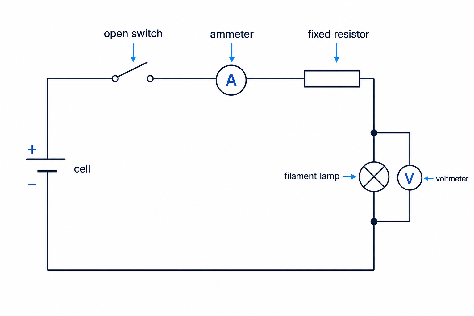
Draw a circuit with one cell, an open switch, an ammeter, a fixed resistor, and a filament lamp in the main circuit. Add a voltmeter to measure the potential difference across the lamp.
-
The cell, switch, ammeter, fixed resistor, and lamp are described as being in the main circuit, so place them around one conducting loop.
-
The switch should be open, so draw it with a clear gap to show that the circuit is not complete until the switch is closed.
-
The ammeter must measure the main circuit current, so keep it in series in the main loop rather than across a component.
-
The voltmeter must measure the potential difference across the lamp, so connect it to the two nodes on either side of the lamp, forming a parallel branch.
-
Add filled junction dots where the voltmeter branch joins the main circuit so the connections are unambiguous.
The resulting circuit diagram could be drawn like this:
Reading a circuit diagram
When interpreting a diagram, do not just scan from left to right. Trace the actual conducting paths.
Ask yourself:
- Where are the terminals of the supply?
- Is there a complete path for current?
- Where can current split into branches?
- Which components are connected between the same two nodes?
- Are the meters in sensible positions?
For example, in the diagram above, the voltmeter is connected across the lamp only. It is not across the fixed resistor, because its two leads connect to the two nodes either side of the lamp.
Topology beats geography
If two diagrams have the same components connected to the same nodes, they represent the same circuit, even if the symbols are arranged in different places on the page.
In the exam
-
Use standard circuit symbols, not sketches of real apparatus.
-
Check meter placement carefully: ammeter in series, voltmeter in parallel.
-
Mark junctions clearly with dots and avoid ambiguous wire crossings.
-
Remember that the shape of the diagram is less important than which components are connected to which nodes.
Check yourself
- What feature of the cell symbol shows which terminal is positive?
- How would you show that two crossing wires are connected?
- Where should you place an ammeter and a voltmeter to measure the current through, and potential difference across, a lamp?