

What you'll learn
- What capacitance means, and how to use C=QVC = \frac{Q}{V}C=VQ.
- How electrons move when a capacitor charges or discharges.
- How to find the total capacitance of capacitors in series and in parallel.
- How resistors, ammeters and voltmeters are used in capacitor circuits and practical investigations.
The basic circuit ideas you already need
A charge is a quantity of electricity, measured in coulombs (C). We normally use the symbol QQQ for charge.
A potential difference is the energy transferred per unit charge between two points, measured in volts (V). We normally use the symbol VVV.
A current is the rate of flow of charge, measured in amperes (A). In metal wires, the moving charged particles are electrons, but conventional current is defined as the direction a positive charge would move. So in metal wires, electron flow is opposite to conventional current.
What is a capacitor?
A capacitor is a component made from two conducting plates separated by an insulator. The insulator is often called a dielectric, meaning a material that does not allow charge to flow through it easily.
When connected to a power supply, one plate becomes positively charged and the other becomes negatively charged. The capacitor stores energy in the electric field between the plates.
Capacitance
The capacitance of a capacitor is the charge stored per unit potential difference across it:
C=QVC = \frac{Q}{V}C=VQwhere CCC is capacitance in farads (F), QQQ is the magnitude of the charge on one plate in coulombs (C), and VVV is the potential difference across the capacitor in volts (V).
One farad means one coulomb per volt:
1 F=1 C V−11\,\text{F} = 1\,\text{C}\,\text{V}^{-1}1F=1CV−1In practice, one farad is very large, so you often meet microfarads (µF), nanofarads (nF) and picofarads (pF).
Charge on a capacitor is not its net charge
When a question says “the charge on the capacitor”, it means the magnitude of the charge on one plate. The plates have equal and opposite charges, so the whole capacitor is still electrically neutral overall.
Finding charge stored
A 220 µF capacitor is connected across a 9.0 V supply. Calculate the charge stored on one plate.
-
Convert the capacitance into farads: 220 μF=220×10−6 F=2.20×10⁻⁴ F220\,\mu\text{F} = 220 \times 10^{-6}\,\text{F} = 2.20 \times 10^{-4}\,\text{F}220μF=220×10−6F=2.20×10⁻⁴F.
-
Rearrange C=QVC = \frac{Q}{V}C=VQ to give Q=CVQ = CVQ=CV, then substitute:
Q=(2.20×10⁻⁴ F)(9.0 V)Q = (2.20 \times 10^{-4}\,\text{F})(9.0\,\text{V})Q=(2.20×10⁻⁴F)(9.0V) -
Calculate the charge:
Q=1.98×10⁻³ C≈2.0×10⁻³ CQ = 1.98 \times 10^{-3}\,\text{C} \approx 2.0 \times 10^{-3}\,\text{C}Q=1.98×10⁻³C≈2.0×10⁻³CSo the plates carry charges of approximately +2.0×10⁻³ C+2.0 \times 10^{-3}\,\text{C}+2.0×10⁻³C and −2.0×10⁻³ C-2.0 \times 10^{-3}\,\text{C}−2.0×10⁻³C.
Charging and discharging a capacitor
When a capacitor is charging, electrons do not cross the insulating gap between the plates. Instead, electrons move around the external circuit.
If the top plate is connected to the positive terminal of a d.c. supply, electrons are pulled away from that plate, so it becomes positive. At the same time, electrons are pushed onto the plate connected to the negative terminal, so it becomes negative.
When a capacitor is discharging, the supply is removed and the two plates are connected through a conducting path, often including a resistor. Electrons move from the negative plate through the external circuit to the positive plate, reducing the charge separation.
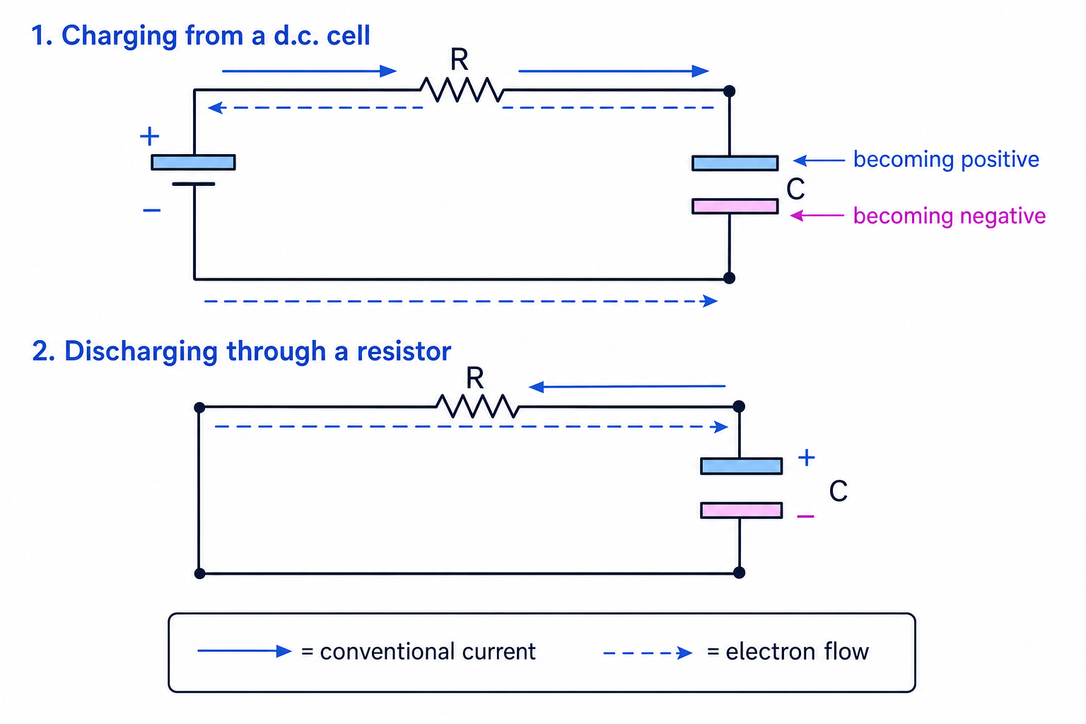
Charging through a resistor
A 470 µF capacitor is initially uncharged and is connected to a 12 V d.c. supply through a 2.2 kΩ resistor. Find the initial current and the final charge on the capacitor.
-
At the instant of connection, the capacitor is uncharged, so the potential difference across it is zero. The full 12 V is across the resistor.
-
Use Ohm’s law for the initial current:
I0=VR=12 V2.2×103 ΩI_0 = \frac{V}{R} = \frac{12\,\text{V}}{2.2 \times 10^3\,\Omega}I0=RV=2.2×10³Ω12V I0=5.45×10⁻³ A≈5.5 mAI_0 = 5.45 \times 10^{-3}\,\text{A} \approx 5.5\,\text{mA}I0=5.45×10⁻³A≈5.5mA -
After a long time, the capacitor is fully charged. The current is zero, so the resistor has zero potential difference across it. The capacitor has 12 V across it, so:
Q=CV=(470×10−6 F)(12 V)Q = CV = (470 \times 10^{-6}\,\text{F})(12\,\text{V})Q=CV=(470×10−6F)(12V) Q=5.64×10⁻³ C≈5.6 mCQ = 5.64 \times 10^{-3}\,\text{C} \approx 5.6\,\text{mC}Q=5.64×10⁻³C≈5.6mC
Resistors in capacitor circuits
A resistor in series with a capacitor limits the current. During charging, the capacitor’s potential difference increases, so the resistor’s potential difference decreases. That means the current decreases.
For a simple series charging circuit:
Vsupply=VR+VCV_\text{supply} = V_R + V_CVsupply=VR+VCand since VR=IRV_R = IRVR=IR,
Vsupply=IR+VCV_\text{supply} = IR + V_CVsupply=IR+VCYou do not need the exponential charging equations for this section, but you should be confident with the initial and final states:
- just after connection, an uncharged capacitor has VC=0V_C = 0VC=0;
- after a long time in a d.c. circuit, an ideal fully charged capacitor has no current through it;
- during discharge, the current gradually falls as the capacitor loses charge.
Capacitors in series
Capacitors are in series when they are connected one after another in a single path.
In series, each capacitor stores the same magnitude of charge. The supply potential difference is split between the capacitors.
For two or more capacitors in series:
1C=1C1+1C2+⋯\frac{1}{C} = \frac{1}{C_1} + \frac{1}{C_2} + \cdotsC1=C11+C21+⋯where CCC is the total capacitance.
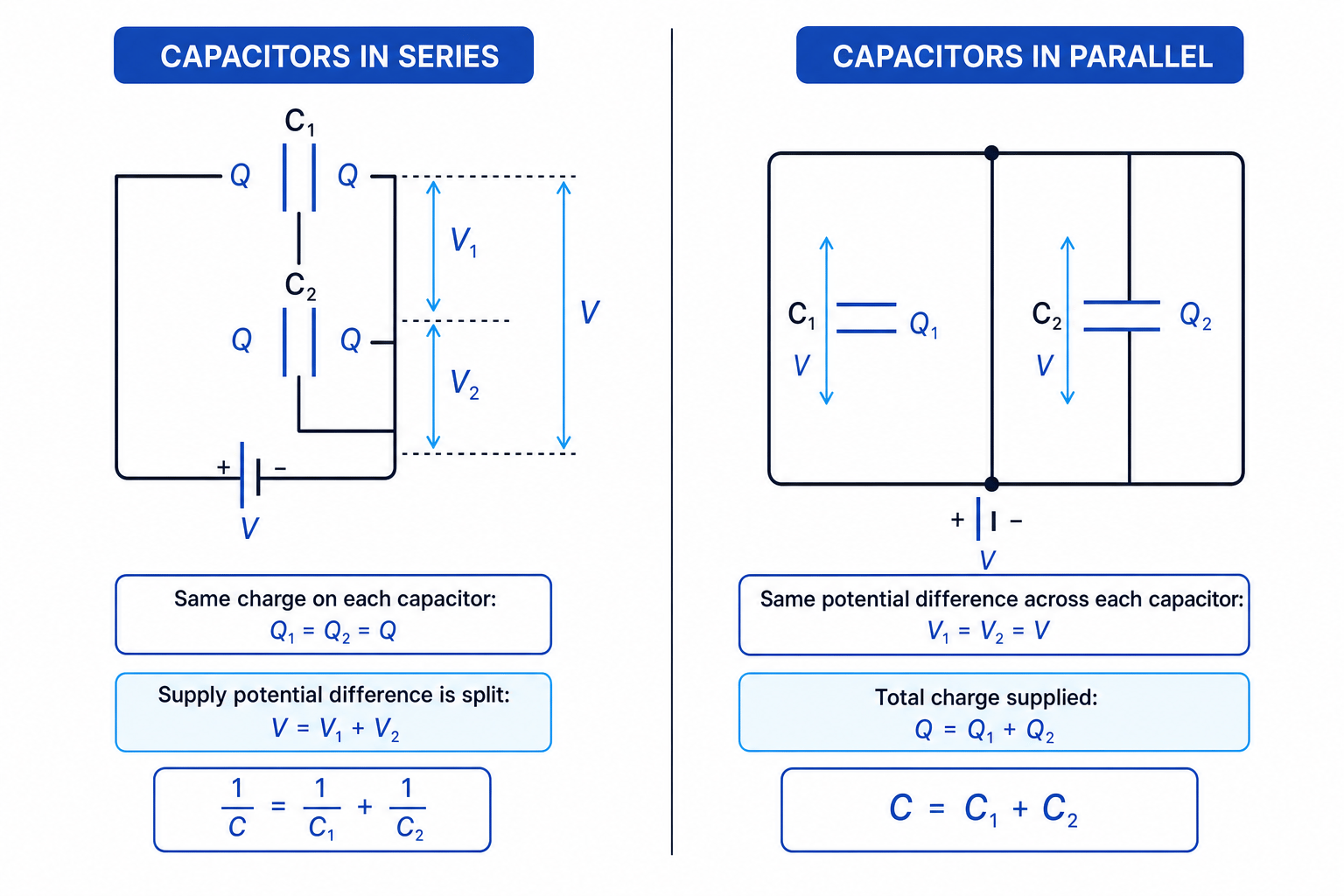
Capacitors in series
A 4.7 µF capacitor and a 10 µF capacitor are connected in series across a 12 V supply. Find the total capacitance and the potential difference across each capacitor.
-
Use the series rule:
C=(14.7 μF+110 μF)−1C = \left(\frac{1}{4.7\,\mu\text{F}} + \frac{1}{10\,\mu\text{F}}\right)^{-1}C=(4.7μF1+10μF1)−1 C=3.20 μF≈3.2 μFC = 3.20\,\mu\text{F} \approx 3.2\,\mu\text{F}C=3.20μF≈3.2μF -
In series, each capacitor has the same charge. The total charge supplied is:
Q=CV=(3.20×10⁻⁶ F)(12 V)Q = CV = (3.20 \times 10^{-6}\,\text{F})(12\,\text{V})Q=CV=(3.20×10⁻⁶F)(12V) Q=3.84×10⁻⁵ C=38 μCQ = 3.84 \times 10^{-5}\,\text{C} = 38\,\mu\text{C}Q=3.84×10⁻⁵C=38μC -
Use V=QCV = \frac{Q}{C}V=CQ for each capacitor:
V1=38.4 μC4.7 μF=8.2 VV_1 = \frac{38.4\,\mu\text{C}}{4.7\,\mu\text{F}} = 8.2\,\text{V}V1=4.7μF38.4μC=8.2V V2=38.4 μC10 μF=3.8 VV_2 = \frac{38.4\,\mu\text{C}}{10\,\mu\text{F}} = 3.8\,\text{V}V2=10μF38.4μC=3.8VThe voltages add to 12 V, as they should.
Capacitors in parallel
Capacitors are in parallel when each capacitor is connected across the same two points in the circuit.
In parallel, each capacitor has the same potential difference across it. The total charge supplied is the sum of the charges stored on the individual capacitors.
For two or more capacitors in parallel:
C=C1+C2+⋯C = C_1 + C_2 + \cdotsC=C1+C2+⋯Capacitors in parallel
A 4.7 µF capacitor and a 10 µF capacitor are connected in parallel across a 12 V supply. Find the total capacitance and the total charge stored.
-
Add the capacitances directly:
C=4.7 μF+10 μF=14.7 μFC = 4.7\,\mu\text{F} + 10\,\mu\text{F} = 14.7\,\mu\text{F}C=4.7μF+10μF=14.7μF -
Each capacitor has the full 12 V across it, so the charges are:
Q1=(4.7×10⁻⁶ F)(12 V)=56 μCQ_1 = (4.7 \times 10^{-6}\,\text{F})(12\,\text{V}) = 56\,\mu\text{C}Q1=(4.7×10⁻⁶F)(12V)=56μC Q2=(10×10−6 F)(12 V)=120 μCQ_2 = (10 \times 10^{-6}\,\text{F})(12\,\text{V}) = 120\,\mu\text{C}Q2=(10×10−6F)(12V)=120μC -
Add the charges:
Q=Q1+Q2=176 μC≈1.8×10⁻⁴ CQ = Q_1 + Q_2 = 176\,\mu\text{C} \approx 1.8 \times 10^{-4}\,\text{C}Q=Q1+Q2=176μC≈1.8×10⁻⁴C
Quick check for combinations
Capacitors behave opposite to resistors for the total value: capacitors in series give a total capacitance smaller than the smallest individual capacitor, while capacitors in parallel give a total capacitance larger than the largest individual capacitor.
Investigating capacitor combinations practically
To investigate capacitors in series and parallel, you can build the combination as a “capacitor bank” and measure how it charges or discharges.
A typical method uses:
- an ammeter in series to measure current;
- a voltmeter in parallel across the capacitor bank to measure potential difference;
- a resistor in series to limit current and make changes easier to measure;
- a switch so you can charge and discharge the capacitors safely.
One useful approach is to charge the capacitor bank to a measured voltage, then discharge it through a resistor while recording current against time. The area under the current-time graph gives the charge transferred, because current is the rate of flow of charge. Then use C=QVC = \frac{Q}{V}C=VQ.
Charged capacitors can surprise you
A capacitor can remain charged after the supply is disconnected. In practical work, discharge it through a suitable resistor before handling or changing the circuit, and do not exceed the voltage rating of the capacitor.
Estimating capacitance from discharge data
A capacitor combination is charged to 6.0 V. When it is discharged through a resistor, the area under the current-time graph is 2.9×10⁻³ C2.9 \times 10^{-3}\,\text{C}2.9×10⁻³C. Estimate the total capacitance.
-
Interpret the graph area as the charge transferred during discharge:
Q=2.9×10⁻³ CQ = 2.9 \times 10^{-3}\,\text{C}Q=2.9×10⁻³C -
Use the capacitance equation:
C=QV=2.9×10⁻³ C6.0 VC = \frac{Q}{V} = \frac{2.9 \times 10^{-3}\,\text{C}}{6.0\,\text{V}}C=VQ=6.0V2.9×10−3C -
Calculate the capacitance:
C=4.8×10⁻⁴ F=480 μFC = 4.8 \times 10^{-4}\,\text{F} = 480\,\mu\text{F}C=4.8×10⁻⁴F=480μF
In the exam
- Decide first whether the capacitors are in series or parallel; the rules are not the same as for resistors.
- In C=QVC = \frac{Q}{V}C=VQ, use the charge on one plate, not the net charge of the whole capacitor.
- For d.c. circuits with resistors, compare the initial state with the long-time state.
- In practical questions, place ammeters in series, voltmeters in parallel, and use the area under an current-time graph to find charge if needed.
Check yourself
- Why does a fully charged capacitor eventually stop taking current from a d.c. supply?
- Two capacitors are connected in series. Why is the charge on each capacitor the same?
- How would you use an ammeter and voltmeter to estimate the total capacitance of a parallel combination?
