

What you'll learn
- How X-rays, ultrasound, MRI and radioactive tracers form medical images.
- How to use attenuation, acoustic impedance, Doppler, Larmor frequency and dose equations.
- How to compare imaging methods in terms of resolution, contrast, risk and patient suitability.
- How nuclear medicine uses gamma cameras and PET to show body function, not just anatomy.
The big idea: imaging needs contrast
Medical imaging works when different tissues produce different signals. This difference is called contrast. For example, bone absorbs X-rays more strongly than soft tissue, while MRI contrast depends strongly on hydrogen nuclei and their relaxation times.
Contrast mechanism
For any imaging technique, ask: what enters the body, how does it interact with tissue, what is detected, and what tissue property creates contrast?
X-rays
X-rays
X-rays are high-frequency electromagnetic waves. They are ionising radiation, meaning individual photons can remove electrons from atoms and produce ions, so exposure can damage living tissue.
X-rays travel at the speed of light in vacuum, have no charge or mass, and can penetrate soft tissue. Their attenuation depends on photon energy, tissue thickness, density and atomic number. Bone, which contains higher atomic number material than soft tissue, attenuates X-rays more strongly.
Producing X-rays and X-ray spectra
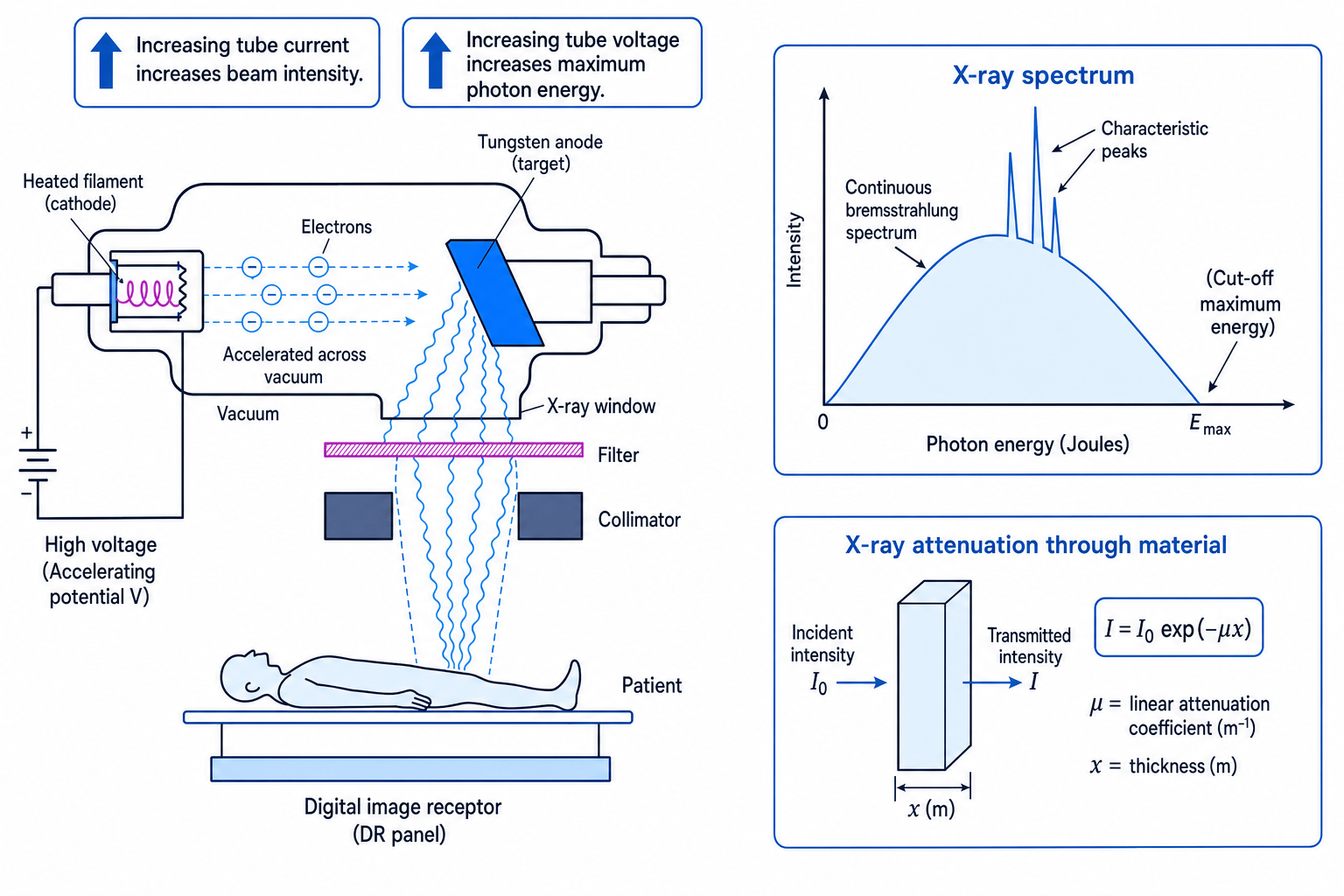
In an X-ray tube, a heated filament cathode releases electrons by thermionic emission. A large potential difference accelerates the electrons across a vacuum towards a metal target, often tungsten. When the electrons decelerate rapidly in the target, they emit X-rays.
There are two parts to the spectrum:
- Bremsstrahlung radiation: a continuous spectrum produced by braking electrons.
- Characteristic X-rays: sharp peaks caused by electron transitions between energy levels in the target atoms.
The tube current controls the number of electrons striking the target per second, so it controls beam intensity. The tube voltage controls the maximum kinetic energy of the electrons, so it controls the maximum photon energy. Filtration removes low-energy X-rays that would be absorbed near the skin and add dose without improving the image; collimation narrows the beam to the region needed.
Current and voltage are not the same control
Increasing tube current mainly increases the number of X-ray photons. Increasing tube voltage increases the maximum photon energy and usually makes the beam more penetrating.
X-ray attenuation
As X-rays pass through matter, their intensity decreases exponentially:
I=I0exp(−μx)I = I_0 \exp(-\mu x)I=I0exp(−μx)where I0I_0I0 is the incident intensity, III is the transmitted intensity, xxx is thickness in metres, and μ\muμ is the linear attenuation coefficient in m⁻¹.
Calculating transmitted X-ray intensity
An X-ray beam passes through 0.040 m of tissue with μ=18 m−1\mu = 18\ \text{m}^{-1}μ=18 m−1. Find the fraction transmitted.
-
Use the ratio form so the initial intensity cancels:
II0=exp(−μx)\frac{I}{I_0} = \exp(-\mu x)I0I=exp(−μx) -
Substitute the thickness in metres:
II0=exp[−(18 m−1)(0.040 m)]=exp(−0.72)\frac{I}{I_0} = \exp[-(18\ \text{m}^{-1})(0.040\ \text{m})] = \exp(-0.72)I0I=exp[−(18 m−1)(0.040 m)]=exp(−0.72) -
Evaluate the exponential:
II0=0.49\frac{I}{I_0} = 0.49I0I=0.49So about 49 percent of the incident intensity is transmitted.
Finding an attenuation coefficient from data
Taking logs gives lnI=lnI0−μx\ln I = \ln I_0 - \mu xlnI=lnI0−μx, so a graph of lnI\ln IlnI against xxx has gradient −μ-\mu−μ.
Diagnosis, therapy, fluoroscopy and CT
Diagnostic X-rays use relatively low photon energies compared with therapy. The aim is to produce enough contrast while keeping dose low. High-energy X-rays are used in radiotherapy to damage tumour DNA and kill cancer cells, with careful planning to reduce dose to healthy tissue.
Soft tissues often have similar attenuation coefficients, so contrast can be poor. Contrast agents containing high atomic number elements may be used to make blood vessels, the gut or urinary system more visible.
Radiography means forming a projection image using X-rays. Modern systems use digital image receptors, which convert the X-ray pattern into electronic signals for display, storage and processing.
Fluoroscopy produces real-time X-ray images, useful for moving structures or guiding procedures. An image intensifier or flat-panel detector converts a weak X-ray image into a brighter electronic image, allowing lower dose than direct viewing.
Computed tomography, or CT, uses a rotating X-ray beam and detectors around the patient. Many projections are taken at different angles, and a computer reconstructs slice images showing the variation of attenuation coefficient through the body. CT gives much better internal detail than a single radiograph, but usually involves a larger dose.
Ultrasound
Ultrasound
Ultrasound is sound with frequency f>20 kHzf > 20\ \text{kHz}f>20 kHz. Medical ultrasound uses high-frequency longitudinal waves sent into the body as short pulses.
Piezoelectric transducers, A-scans and B-scans
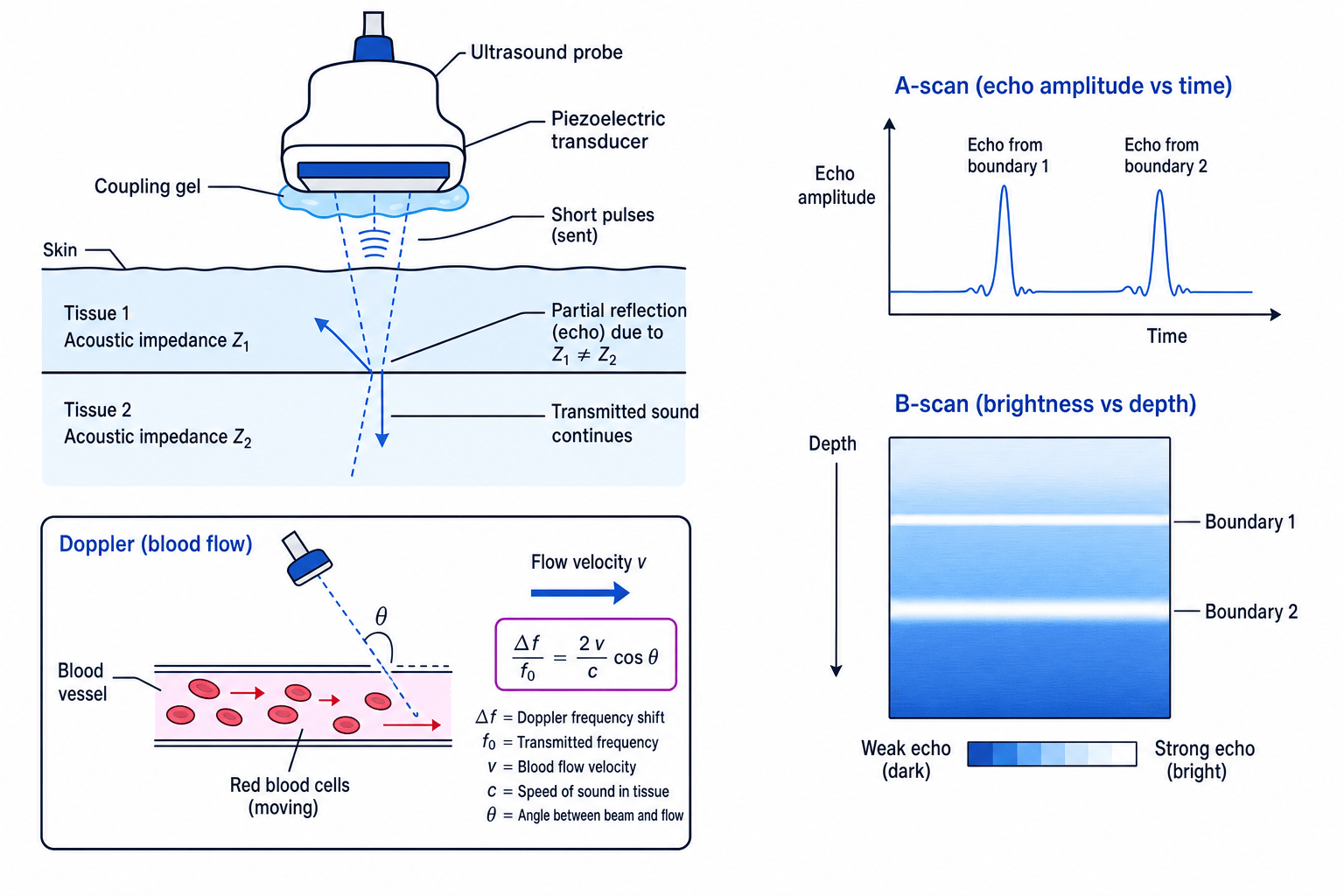
A piezoelectric transducer changes shape when a potential difference is applied, producing ultrasound. The same crystal also generates a potential difference when returning echoes deform it, so it can act as both transmitter and detector.
In an A-scan, echo amplitude is plotted against time. Echo time gives depth because the pulse travels to the boundary and back. A-scans are useful for distance measurements, such as eye measurements. In a B-scan, echo strength is displayed as brightness at the correct position and depth, building up a two-dimensional image, such as fetal, abdominal or heart scans.
Acoustic impedance
The acoustic impedance of a material is
Z=cρZ = c\rhoZ=cρwhere ccc is the speed of sound in the material and ρ\rhoρ is its density. The unit is kg m⁻² s⁻¹. A boundary reflects ultrasound strongly when the acoustic impedances on each side are very different.
Coupling gel is needed because air has a very different acoustic impedance from skin, so an air gap would reflect most of the ultrasound before it entered the body.
Calculating acoustic impedance
Soft tissue has sound speed c=1540 m s−1c = 1540\ \text{m s}^{-1}c=1540 m s−1 and density ρ=1050 kg m−3\rho = 1050\ \text{kg m}^{-3}ρ=1050 kg m−3. Find its acoustic impedance.
-
Use the definition of acoustic impedance:
Z=cρZ = c\rhoZ=cρ -
Substitute both quantities with units:
Z=(1540 m s−1)(1050 kg m−3)Z = (1540\ \text{m s}^{-1})(1050\ \text{kg m}^{-3})Z=(1540 m s−1)(1050 kg m−3) -
Multiply and simplify the units:
Z=1.62×10⁶ kg m−2 s−1Z = 1.62 \times 10^6\ \text{kg m}^{-2}\text{ s}^{-1}Z=1.62×10⁶ kg m−2 s−1A boundary with a similar value gives weak reflection; a boundary with a very different value gives a strong echo.
Doppler ultrasound and blood flow
Moving blood cells reflect ultrasound with a changed frequency. For a reflected ultrasound signal,
Δff0=2vccosθ\frac{\Delta f}{f_0} = \frac{2v}{c}\cos\thetaf0Δf=c2vcosθwhere Δf\Delta fΔf is the frequency shift, f0f_0f0 is the transmitted frequency, vvv is blood speed, ccc is the speed of sound in tissue, and θ\thetaθ is the angle between the ultrasound beam and the blood flow direction. The factor of 2 appears because the wave is reflected from moving cells.
Finding blood speed from a Doppler shift
An ultrasound probe sends f0=5.0×10⁶ Hzf_0 = 5.0 \times 10^6\ \text{Hz}f0=5.0×10⁶ Hz into tissue. The measured shift is Δf=3.0×10³ Hz\Delta f = 3.0 \times 10^3\ \text{Hz}Δf=3.0×10³ Hz, with c=1540 m s−1c = 1540\ \text{m s}^{-1}c=1540 m s−1 and θ=60∘\theta = 60^\circθ=60∘. Find vvv.
-
Rearrange the Doppler equation:
v=cΔf2f0cosθv = \frac{c\Delta f}{2f_0\cos\theta}v=2f0cosθcΔf -
Substitute the values:
v=(1540 m s−1)(3.0×10³ Hz)2(5.0×10⁶ Hz)cos60∘v = \frac{(1540\ \text{m s}^{-1})(3.0 \times 10^3\ \text{Hz})}{2(5.0 \times 10^6\ \text{Hz})\cos 60^\circ}v=2(5.0×10⁶ Hz)cos60∘(1540 m s−1)(3.0×10³ Hz) -
Evaluate:
v=0.924 m s−1v = 0.924\ \text{m s}^{-1}v=0.924 m s−1So the blood speed is about 0.92 m s−10.92\ \text{m s}^{-1}0.92 m s−1.
Doppler angle
If θ=90∘\theta = 90^\circθ=90∘, then cosθ=0\cos\theta = 0cosθ=0, so there is no measured Doppler shift. The probe must not be perpendicular to the blood flow.
Magnetic resonance imaging
MRI uses hydrogen nuclei, mainly protons, in the body. In a strong magnetic field, these nuclei precess, meaning their magnetic moments rotate around the field direction. They absorb radio-frequency energy strongly at the Larmor frequency. After the radio-frequency pulse is removed, the nuclei relax back towards equilibrium, emitting signals detected by receiver coils.
Different tissues have different proton densities and relaxation times, so MRI gives excellent soft-tissue contrast. Magnetic field gradients are used to encode position and reconstruct images of slices through the body.
The Larmor frequency is
f=42.6×10⁶Bf = 42.6 \times 10^6 Bf=42.6×10⁶Bwhere fff is in hertz and BBB is magnetic flux density in tesla.
Calculating the Larmor frequency
Find the Larmor frequency for protons in a 1.5 T MRI scanner.
-
Use the given relationship:
f=42.6×10⁶Bf = 42.6 \times 10^6 Bf=42.6×10⁶B -
Substitute B=1.5 TB = 1.5\ \text{T}B=1.5 T:
f=(42.6×10⁶ Hz T−1)(1.5 T)f = (42.6 \times 10^6\ \text{Hz T}^{-1})(1.5\ \text{T})f=(42.6×10⁶ Hz T−1)(1.5 T) -
Calculate:
f=6.39×10⁷ Hzf = 6.39 \times 10^7\ \text{Hz}f=6.39×10⁷ HzThis is 63.9 MHz.
MRI is especially useful for brain, spinal cord, joint and tumour imaging. It does not use ionising radiation, but it is expensive, relatively slow, noisy, and unsuitable for some patients with pacemakers, ferromagnetic implants or severe claustrophobia.
Comparing ultrasound, X-ray imaging and MRI
| Method | Main strengths | Main limitations |
|---|---|---|
| X-ray radiography and CT | Fast; good for bone, chest imaging and trauma; CT gives detailed slices | Ionising radiation; soft tissue contrast can be poor without contrast agents; CT dose is higher than a single radiograph |
| Ultrasound | Non-ionising; portable; cheap; real-time; useful in pregnancy and blood-flow studies | Poor through bone or gas; operator-dependent; lower resolution than CT or MRI in many cases |
| MRI | Excellent soft-tissue contrast; no ionising radiation; many contrast mechanisms | Expensive; slow; safety issues with metal implants; less useful for cortical bone |
Benefit versus risk
For any medical exposure to ionising radiation, the clinical benefit must outweigh the risk, and the dose should be kept as low as reasonably practicable.
Radiation effects and dose
Alpha radiation is helium nuclei, beta radiation is high-speed electrons or positrons, and gamma radiation is electromagnetic radiation. All can ionise atoms in living tissue, damaging DNA directly or indirectly through free radicals.
Alpha radiation is highly ionising but weakly penetrating, so it is especially dangerous if taken inside the body. Beta radiation is moderately penetrating and ionising. Gamma radiation is less ionising per unit path length but highly penetrating, so it can be an external whole-body hazard.
Dose quantities
- Absorbed dose DDD is energy absorbed per kilogram, measured in gray, Gy, where 1 Gy is 1 J kg⁻¹.
- Equivalent dose HHH accounts for radiation type: H=DWRH = DW_RH=DWR, measured in sievert, Sv.
- Effective dose EEE accounts for tissue sensitivity: E=HWTE = HW_TE=HWT, also measured in sievert, Sv.
Calculating effective dose
A tissue mass of 0.60 kg absorbs 2.4×10⁻³ J2.4 \times 10^{-3}\ \text{J}2.4×10⁻³ J from beta radiation. Take WR=1W_R = 1WR=1 and WT=0.12W_T = 0.12WT=0.12. Find the effective dose.
-
Calculate absorbed dose:
D=2.4×10⁻³ J0.60 kg=4.0×10⁻³ GyD = \frac{2.4 \times 10^{-3}\ \text{J}}{0.60\ \text{kg}} = 4.0 \times 10^{-3}\ \text{Gy}D=0.60 kg2.4×10−3 J=4.0×10⁻³ Gy -
Apply the radiation weighting factor:
H=DWR=(4.0×10⁻³ Gy)(1)=4.0×10⁻³ SvH = DW_R = (4.0 \times 10^{-3}\ \text{Gy})(1) = 4.0 \times 10^{-3}\ \text{Sv}H=DWR=(4.0×10⁻³ Gy)(1)=4.0×10⁻³ Sv -
Apply the tissue weighting factor:
E=HWT=(4.0×10⁻³ Sv)(0.12)=4.8×10⁻⁴ SvE = HW_T = (4.0 \times 10^{-3}\ \text{Sv})(0.12) = 4.8 \times 10^{-4}\ \text{Sv}E=HWT=(4.0×10⁻³ Sv)(0.12)=4.8×10⁻⁴ Sv
Radionuclide imaging, gamma cameras and PET
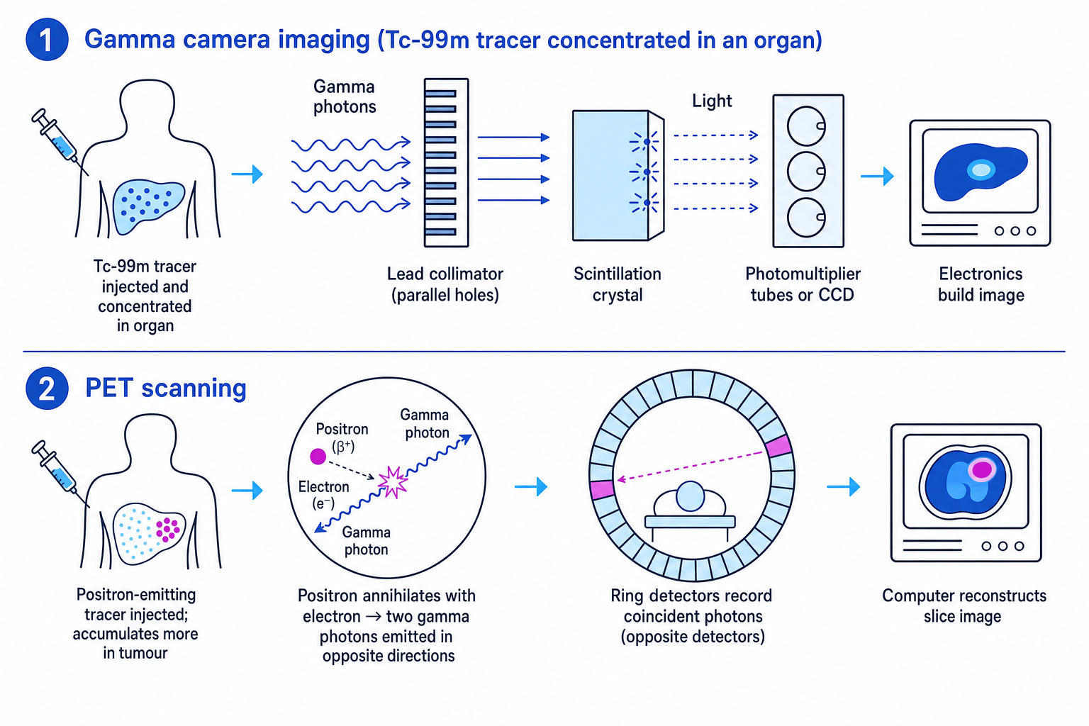
A radionuclide tracer is a radioactive substance introduced into the body in a small quantity to follow a biological process. Technetium-99m is widely used because it emits gamma radiation suitable for detection, has a short half-life of about six hours, and can be attached to compounds that target particular organs.
A gamma camera detects gamma photons leaving the patient. A lead collimator only allows photons travelling in certain directions to reach the detector, giving positional information. A scintillation crystal converts gamma photons into flashes of light. Photomultiplier tubes or a CCD detect and amplify the light signal, and electronics build an image of tracer distribution.
In positron emission tomography, or PET, a positron-emitting tracer is injected. The positron annihilates with an electron, producing two gamma photons travelling in opposite directions. A ring of detectors records coincident photon arrivals and reconstructs where the annihilation occurred. Tumours can appear as “hot spots” because many have high metabolic activity and take up more tracer.
In the exam
- For each imaging method, state the source, tissue interaction, detector, contrast mechanism and one limitation.
- In calculations, convert thickness to metres, use hertz for frequency, and keep dose units distinct: Gy for absorbed dose, Sv for equivalent or effective dose.
- In evaluation questions, balance image quality and diagnostic benefit against dose, cost, availability and patient safety.
Check yourself
- Why does coupling gel improve ultrasound transmission into the body?
- How do tube current and tube voltage affect an X-ray beam differently?
- Why can PET scans be useful for detecting tumours rather than only showing anatomy?
