

What you'll learn
- How a rotating coil in a magnetic field produces a sinusoidal induced emf.
- What peak, period, frequency and rms values mean for a.c. waveforms.
- How inductors and capacitors affect phase and oppose a.c. using reactance.
- How phasors, impedance, resonance frequency and Q factor describe series RCL circuits.
1. Rotating coils and electromagnetic induction
An alternating current, or a.c., is a current whose direction changes periodically. In this option, you mostly deal with sinusoidal a.c., meaning it varies like a sine or cosine wave.
A rotating coil in a magnetic field is the basic model of an a.c. generator: mechanical rotation changes the magnetic flux linkage, so an emf is induced.
Faraday's law
Faraday’s law says that the induced emf is equal to the negative rate of change of flux linkage:
V=−Δ(NΦ)ΔtV = -\frac{\Delta(N\Phi)}{\Delta t}V=−ΔtΔ(NΦ)For a smoothly rotating coil, this becomes a calculus idea: the induced emf depends on how fast the flux linkage is changing.
Flux linkage in a rotating coil
Magnetic flux, Φ\PhiΦ, through a flat coil depends on the component of magnetic field perpendicular to the coil:
Φ=BAcosθ\Phi = BA\cos\thetaΦ=BAcosθwhere BBB is magnetic flux density in tesla (T), AAA is area in square metres (m²), and θ\thetaθ is the angle between the coil’s normal and the field.
For a coil with NNN turns, the flux linkage is:
NΦ=BANcosθN\Phi = BAN\cos\thetaNΦ=BANcosθIf the coil rotates at angular speed ω\omegaω, then:
θ=ωt\theta = \omega tθ=ωtso the flux linkage becomes:
NΦ=BANcosωtN\Phi = BAN\cos \omega tNΦ=BANcosωtThe induced emf is therefore:
V=−ddt(BANcosωt)=ωBANsinωtV = -\frac{d}{dt}(BAN\cos \omega t) = \omega BAN\sin\omega tV=−dtd(BANcosωt)=ωBANsinωtThe peak emf is:
V0=ωBANV_0 = \omega BANV0=ωBAN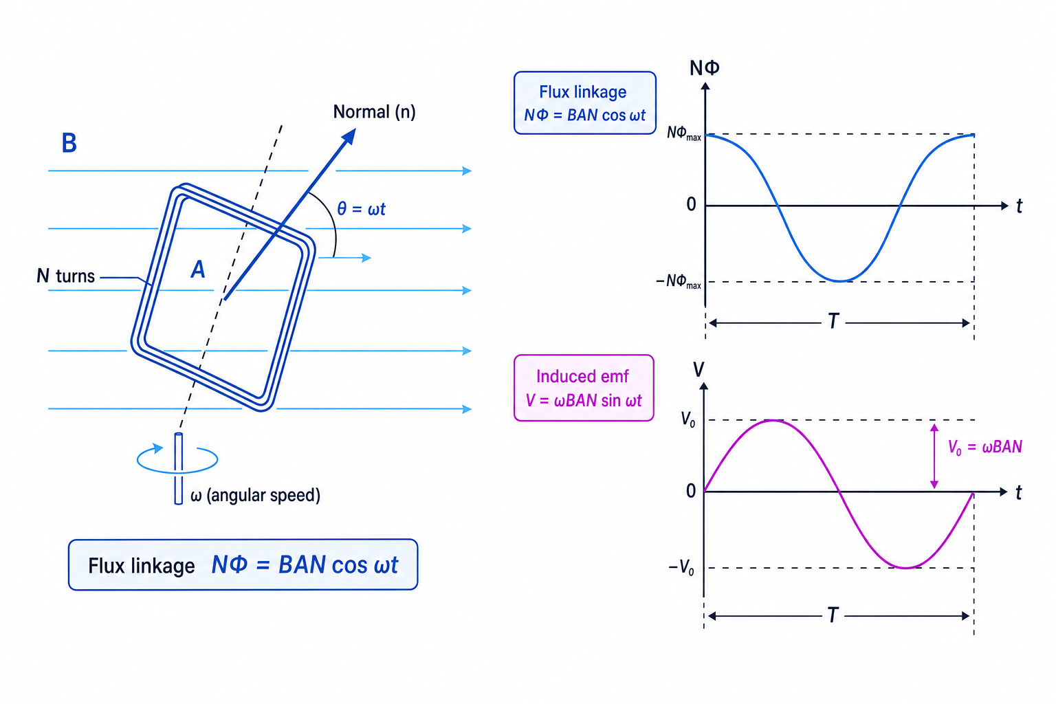
Generator waveform
The flux linkage is greatest when the coil normal is parallel to the magnetic field, but the induced emf is greatest when the flux linkage is changing fastest.
Finding the rms emf and power from a rotating coil
A coil has 200 turns, area 4.0×10⁻³ m24.0 \times 10^{-3}\ \text{m}^24.0×10⁻³ m2, and rotates at 50 Hz in a uniform magnetic field of 0.20 T. It is connected to a 40 Ω resistor. Find the peak emf, rms emf and mean power dissipated.
- Convert frequency to angular speed:
- Use the peak emf equation:
- Convert peak emf to rms emf:
- Use rms values for mean power in the resistor:
2. Describing a.c. waveforms
Waveform terms
For an alternating potential difference or current:
- Frequency, fff, is the number of complete cycles per second, measured in hertz (Hz).
- Period, TTT, is the time for one complete cycle, measured in seconds (s), with T=1/fT = 1/fT=1/f.
- Peak value, such as V0V_0V0 or I0I_0I0, is the maximum magnitude from zero.
- Rms value means “root mean square”: the equivalent d.c. value that gives the same mean power dissipation in a resistor.
For a sinusoidal current or potential difference:
I=I02I = \frac{I_0}{\sqrt{2}}I=2I0 V=V02V = \frac{V_0}{\sqrt{2}}V=2V0Here, III and VVV are rms values unless otherwise stated. For the rotating coil:
Vrms=ωBAN2V_{\text{rms}} = \frac{\omega BAN}{\sqrt{2}}Vrms=2ωBANMean power in a resistor
For a resistor in an a.c. circuit, use rms values in the usual power equations:
P=IV=I2R=V2RP = IV = I^2R = \frac{V^2}{R}P=IV=I2R=RV2Using peak values in power equations
If the question asks for mean power in a resistor, use rms values. Using V0V_0V0 instead of VrmsV_{\text{rms}}Vrms makes the power twice too large for a sinusoidal waveform.
3. Using an oscilloscope
A CRO or PC-based oscilloscope displays potential difference on the vertical axis and time on the horizontal axis.
To measure:
- a.c. potential difference: measure peak-to-peak height, then convert to peak or rms if sinusoidal
- d.c. potential difference: measure the vertical displacement from the zero line
- frequency: measure the period from the time base, then use f=1/Tf = 1/Tf=1/T
- current: measure the potential difference across a known resistor and use I=V/RI = V/RI=V/R
Oscilloscopes and mains electricity
Do not connect an oscilloscope directly to mains circuits unless the equipment and probes are rated and the setup is safely isolated. UK mains is about 230 V rms, which has a peak value of about 325 V.
Reading a sinusoidal waveform from an oscilloscope
A sine wave is displayed with 5.6 divisions peak-to-peak. The vertical scale is 0.50 V per division. One cycle takes 4.0 divisions, and the time base is 2.0 ms per division. The waveform is across a 10.0 Ω resistor.
- Find the peak-to-peak potential difference:
- Convert peak-to-peak to peak, then to rms:
- Find the period:
- Calculate frequency and rms current:
4. Inductors and capacitors in a.c.
A resistor dissipates energy as heat. An ideal inductor or capacitor stores energy temporarily and returns it to the circuit, so its mean power dissipation is zero.
Reactance
Reactance is the opposition of an inductor or capacitor to alternating current. It is measured in ohms (Ω) and is defined using rms values:
X=VrmsIrmsX = \frac{V_{\text{rms}}}{I_{\text{rms}}}X=IrmsVrmsInductor: current lags potential difference
For an ideal inductor, the current lags behind the potential difference by 90°.
Its reactance is:
XL=ωLX_L = \omega LXL=ωLwhere LLL is inductance in henries (H). Increasing frequency increases inductive reactance.
Capacitor: current leads potential difference
For an ideal capacitor, the current leads the potential difference by 90°.
Its reactance is:
XC=1ωCX_C = \frac{1}{\omega C}XC=ωC1where CCC is capacitance in farads (F). Increasing frequency decreases capacitive reactance.
Comparing inductive and capacitive reactance
A 12.0 V rms, 50 Hz supply is connected separately to a 0.25 H inductor and a 10 µF capacitor. Find the rms current in each ideal component and state the phase relationship.
- Calculate angular frequency:
- For the inductor:
The current lags the potential difference by 90°.
- For the capacitor:
The current leads the potential difference by 90°.
5. Phasors, phase angle and impedance
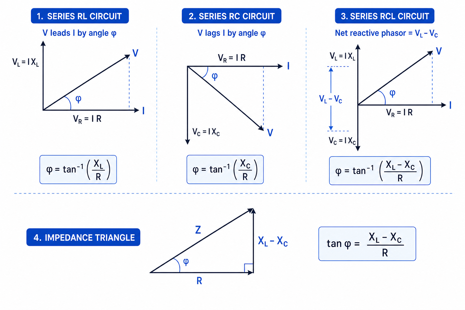
A phasor is a rotating vector used to represent a sinusoidal quantity. In series a.c. circuits, the current is the same through every component, so it is usually taken as the horizontal reference phasor.
Potential differences must be added as phasors, not just as ordinary scalar numbers, because they may not be in phase.
Impedance and phase angle
Impedance, ZZZ, is the total opposition of a circuit to a.c.:
Z=VrmsIrmsZ = \frac{V_{\text{rms}}}{I_{\text{rms}}}Z=IrmsVrmsThe phase angle, ϕ\phiϕ, is the angle between the supply potential difference and the current.
For a series RCL circuit:
Z=R2+(XL−XC)2Z = \sqrt{R^2 + (X_L - X_C)^2}Z=R2+(XL−XC)2and
tanϕ=XL−XCR\tan\phi = \frac{X_L - X_C}{R}tanϕ=RXL−XCIf XL>XCX_L > X_CXL>XC, the circuit is overall inductive, so the current lags the supply potential difference. If XC>XLX_C > X_LXC>XL, it is overall capacitive, so the current leads.
Calculating impedance and phase angle
A series RCL circuit has R=60 ΩR = 60\ \OmegaR=60 Ω, L=0.20 HL = 0.20\ \text{H}L=0.20 H and C=50 μFC = 50\ \mu\text{F}C=50 μF. It is connected to a 12.0 V rms supply at 100 Hz. Find the current and phase angle.
- Calculate the reactances:
- Find the net reactance and impedance:
- Use Z=V/IZ = V/IZ=V/I:
- Calculate the phase angle:
Since XL>XCX_L > X_CXL>XC, the circuit is inductive: the supply potential difference leads the current by 57.5°.
6. Resonance in a series RCL circuit
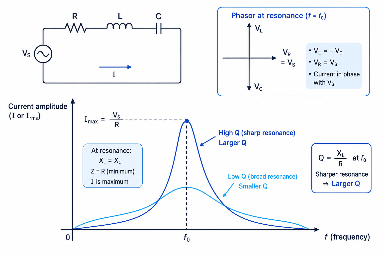
In a series RCL circuit, resonance occurs when the inductive and capacitive reactances are equal:
XL=XCX_L = X_CXL=XCUsing XL=ωLX_L = \omega LXL=ωL and XC=1/(ωC)X_C = 1/(\omega C)XC=1/(ωC):
ωL=1ωC\omega L = \frac{1}{\omega C}ωL=ωC1 ω2=1LC\omega^2 = \frac{1}{LC}ω2=LC1So the resonant angular frequency is:
ω0=1LC\omega_0 = \frac{1}{\sqrt{LC}}ω0=LC1and the resonant frequency is:
f0=12πLCf_0 = \frac{1}{2\pi\sqrt{LC}}f0=2πLC1At resonance, the net reactance is zero, so:
Z=RZ = RZ=RThe current is maximum, and the current is in phase with the supply potential difference.
Q factor
At resonance, the potential differences across the inductor and capacitor are equal in magnitude and opposite in phase. They can be much larger than the supply potential difference, but they cancel in the phasor sum.
Q factor
For a series RCL circuit at resonance, the Q factor is:
Q=VLVR=VCVRQ = \frac{V_L}{V_R} = \frac{V_C}{V_R}Q=VRVL=VRVCA larger Q factor means a sharper, narrower resonance curve.
Finding resonance frequency and Q factor
A series RCL circuit has L=0.10 HL = 0.10\ \text{H}L=0.10 H, C=4.0 μFC = 4.0\ \mu\text{F}C=4.0 μF and total resistance R=20 ΩR = 20\ \OmegaR=20 Ω. The rms supply potential difference is 5.0 V. Find the resonance frequency and Q factor.
- Use the resonance formula:
- Calculate the resonant angular frequency:
- At resonance, find the inductive reactance:
- Use Q=VL/VR=XL/RQ = V_L/V_R = X_L/RQ=VL/VR=XL/R at resonance:
- Since VRV_RVR equals the supply potential difference at resonance:
The inductor and capacitor each have about 40 V rms across them, even though the supply is only 5.0 V rms.
Spotting resonance experimentally
To investigate resonance, keep the supply amplitude constant, vary the frequency, measure the rms current, and plot current against frequency. The peak gives f0f_0f0, and a narrower peak means a larger Q factor.
In the exam
- Check whether a value is peak, peak-to-peak or rms before using it in a power or impedance equation.
- For series RCL circuits, calculate XLX_LXL and XCX_CXC first, then decide whether the circuit is inductive or capacitive.
- Use phasor addition for potential differences; do not add VRV_RVR, VLV_LVL and VCV_CVC as simple scalar magnitudes unless they are in phase.
Check yourself
- Why is the induced emf in a rotating coil zero when the flux linkage is maximum?
- In a series RCL circuit with XC>XLX_C > X_LXC>XL, does the current lead or lag the supply potential difference?
- Why can the potential difference across the inductor be larger than the supply potential difference at resonance?
