

What you'll learn
- How to find the direction of magnetic forces on currents and moving charges.
- How to use F=BIlsinθF = BIl\sin\thetaF=BIlsinθ and F=BqvsinθF = Bqv\sin\thetaF=Bqvsinθ safely.
- How current-carrying wires and solenoids produce magnetic fields.
- How Hall probes and particle accelerators use magnetic-field effects.
The basic idea: what a magnetic field does
A magnetic field is a region where magnetic materials, current-carrying conductors, or moving charged particles can experience a force.
Magnetic flux density
Magnetic flux density, symbol BBB, measures the strength of a magnetic field. It is measured in tesla, T. One tesla is equivalent to one newton per ampere per metre, so 1 T=1 N A−1m−11\ \text{T} = 1\ \text{N A}^{-1}\text{m}^{-1}1 T=1 N A−1m−1.
Magnetic fields are vector fields: they have both size and direction. On diagrams:
- a dot means the field is coming out of the page, like the tip of an arrow;
- a cross means the field is going into the page, like the tail of an arrow.
Force on a current-carrying conductor
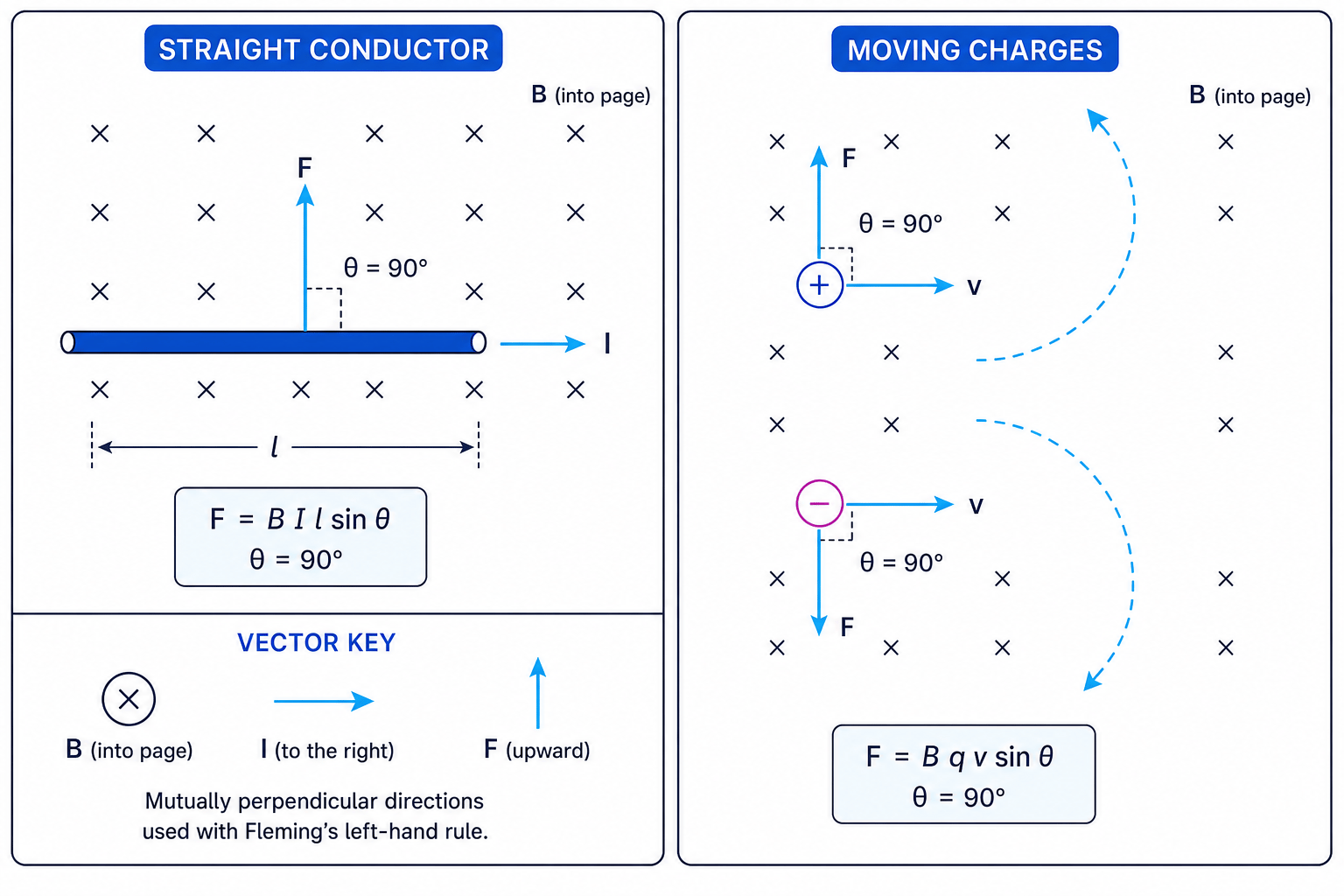
A wire carrying a current in a magnetic field experiences a force if the current is not parallel to the field.
The Eduqas equation is:
F=BIlsinθF = BIl\sin\thetaF=BIlsinθwhere:
- FFF is the force in newtons, N;
- BBB is magnetic flux density in tesla, T;
- III is current in amperes, A;
- lll is the length of wire within the field in metres, m;
- θ\thetaθ is the angle between the current and the magnetic field.
The force is maximum when θ=90∘\theta = 90^\circθ=90∘, because sin90∘=1\sin 90^\circ = 1sin90∘=1. It is zero when the current is parallel to the field.
Direction: Fleming’s left-hand rule
Use Fleming’s left-hand rule for a motor-effect force:
- First finger: magnetic field direction, from north to south.
- Second finger: conventional current direction.
- Thumb: force direction.
For a moving positive charge, treat its velocity as the conventional current direction. For a negative charge, the force is in the opposite direction.
Calculating the force on a wire
A 6.5 cm length of wire carries a current of 3.2 A at right angles to a uniform magnetic field of flux density 0.48 T. Calculate the force on the wire.
-
Convert the length into metres: l=6.5 cm=0.065 ml = 6.5\ \text{cm} = 0.065\ \text{m}l=6.5 cm=0.065 m.
-
Since the wire is at right angles to the field, use sin90∘=1\sin 90^\circ = 1sin90∘=1.
-
Substitute into F=BIlsinθF = BIl\sin\thetaF=BIlsinθ:
F=0.48 T×3.2 A×0.065 m×1F = 0.48\ \text{T} \times 3.2\ \text{A} \times 0.065\ \text{m} \times 1F=0.48 T×3.2 A×0.065 m×1 -
Calculate and round sensibly:
F=0.09984 N≈0.10 NF = 0.09984\ \text{N} \approx 0.10\ \text{N}F=0.09984 N≈0.10 N
Forgetting the angle
Do not automatically use F=BIlF = BIlF=BIl. That only works when the current is perpendicular to the magnetic field. In the general case, use F=BIlsinθF = BIl\sin\thetaF=BIlsinθ.
Practical: force on a current in a magnetic field
A common investigation places a straight wire in the uniform field between magnets. The wire is connected to a power supply and sits on, or is attached to, a balance.
You can measure the force from the change in balance reading:
F=ΔmgF = \Delta m gF=Δmgwhere Δm\Delta mΔm is the change in mass reading in kilograms and ggg is gravitational field strength in newtons per kilogram.
To find BBB, rearrange:
B=FIlsinθB = \frac{F}{Il\sin\theta}B=IlsinθFFor a perpendicular wire, this becomes:
B=FIlB = \frac{F}{Il}B=IlFA good method is to vary III while keeping lll constant, then plot FFF against III. The gradient is BlBlBl, so:
B=gradientlB = \frac{\text{gradient}}{l}B=lgradientMaking the practical reliable
Reverse the current and check that the force reverses. This helps confirm the effect is magnetic rather than due to heating, contact forces, or a zero error on the balance.
Force on a moving charge
A charged particle moving through a magnetic field can also experience a force. The Eduqas equation is:
F=BqvsinθF = Bqv\sin\thetaF=Bqvsinθwhere:
- qqq is the charge in coulombs, C;
- vvv is speed in metres per second, m s⁻¹;
- θ\thetaθ is the angle between the velocity and the magnetic field.
If the velocity is perpendicular to the magnetic field, the force is always perpendicular to the motion. This changes the direction of motion but not the speed, producing circular motion.
Magnetic fields do no work on moving charges
A magnetic force is perpendicular to the velocity of the particle. So it changes the particle’s direction, but not its kinetic energy.
Finding the radius of an ion path
A proton travels at 3.0×10⁶ m s−13.0 \times 10^6\ \text{m s}^{-1}3.0×10⁶ m s−1 perpendicular to a magnetic field of flux density 0.20 T. Calculate the radius of its circular path. Use q=1.60×10⁻¹⁹ Cq = 1.60 \times 10^{-19}\ \text{C}q=1.60×10⁻¹⁹ C and proton mass m=1.67×10⁻²⁷ kgm = 1.67 \times 10^{-27}\ \text{kg}m=1.67×10⁻²⁷ kg.
-
For circular motion, set magnetic force equal to centripetal force:
Bqv=mv2rBqv = \frac{mv^2}{r}Bqv=rmv2 -
Rearrange for radius:
r=mvBqr = \frac{mv}{Bq}r=Bqmv -
Substitute values with units:
r=1.67×10−27 kg×3.0×106 m s−10.20 T×1.60×10−19 Cr = \frac{1.67 \times 10^{-27}\ \text{kg} \times 3.0 \times 10^6\ \text{m s}^{-1}}{0.20\ \text{T} \times 1.60 \times 10^{-19}\ \text{C}}r=0.20 T×1.60×10−19 C1.67×10−27 kg×3.0×106 m s−1 -
Calculate:
r=0.1566 m≈0.16 mr = 0.1566\ \text{m} \approx 0.16\ \text{m}r=0.1566 m≈0.16 m
The Hall effect and Hall voltage
The Hall effect happens when charge carriers moving through a conductor or semiconductor are deflected by a magnetic field.
Here is the process:
- A current flows through a thin conducting strip.
- A magnetic field acts perpendicular to the current.
- Moving charge carriers experience a magnetic force sideways.
- Charge builds up on one side of the strip.
- This creates a transverse potential difference called the Hall voltage, VHV_HVH.
- Eventually, the electric force from the charge separation balances the magnetic force.
For a fixed current in the same Hall probe:
VH∝BV_H \propto BVH∝BSo a Hall probe can be calibrated and used to measure magnetic flux density.
Using a Hall probe calibration
A Hall probe carries a constant current. Its calibration is 24 mV T−124\ \text{mV T}^{-1}24 mV T−1. The measured Hall voltage is 7.2 mV. Find the magnetic flux density.
-
Use the proportional relationship VH=kBV_H = kBVH=kB, where kkk is the calibration constant.
-
Rearrange:
B=VHkB = \frac{V_H}{k}B=kVH -
Substitute:
B=7.2 mV24 mV T−1B = \frac{7.2\ \text{mV}}{24\ \text{mV T}^{-1}}B=24 mV T−17.2 mV -
Calculate:
B=0.30 TB = 0.30\ \text{T}B=0.30 T
Practical: measuring magnetic flux density with a Hall probe
A Hall probe contains a thin semiconductor slice. It is useful because the Hall voltage is usually small but measurable with amplification or a data logger.
In a practical investigation:
- zero the Hall probe away from magnets and currents;
- keep the probe orientation fixed;
- rotate it to find the maximum reading when measuring a field component;
- record readings with distance, current, or position;
- plot suitable graphs, such as BBB against III for a solenoid.
Tilting the Hall probe
A Hall probe measures the component of magnetic field perpendicular to its sensing face. If you tilt it, the reading changes even if the actual field strength has not.
Magnetic fields made by currents
A current-carrying wire produces a magnetic field around it. The direction is found using the right-hand grip rule: point your right thumb in the direction of conventional current, and your fingers curl in the direction of the magnetic field.
For a long straight wire:
B=μ0I2πaB = \frac{\mu_0 I}{2\pi a}B=2πaμ0Iwhere aaa is the radial distance from the wire and μ0\mu_0μ0 is the permeability of free space:
μ0=4π×10−7 T m A−1\mu_0 = 4\pi \times 10^{-7}\ \text{T m A}^{-1}μ0=4π×10−7 T m A−1A solenoid is a long coil of wire. Inside a long solenoid, the field is approximately uniform and parallel to the axis.
For a long solenoid:
B=μ0nIB = \mu_0 nIB=μ0nIwhere nnn is the number of turns per metre.
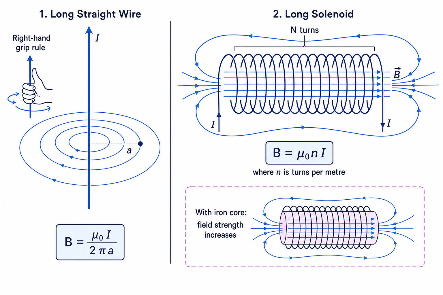
Adding an iron core increases the field strength because the iron becomes magnetised and concentrates the field.
Comparing fields from a wire and a solenoid
A long straight wire carries 8.0 A. Find BBB at a distance of 25 mm. Then find BBB inside a long solenoid with 800 turns in 0.40 m carrying 1.5 A.
-
For the wire, convert the distance: a=25 mm=0.025 ma = 25\ \text{mm} = 0.025\ \text{m}a=25 mm=0.025 m.
-
Substitute into the wire equation:
B=4π×10−7 T m A−1×8.0 A2π×0.025 mB = \frac{4\pi \times 10^{-7}\ \text{T m A}^{-1} \times 8.0\ \text{A}}{2\pi \times 0.025\ \text{m}}B=2π×0.025 m4π×10−7 T m A−1×8.0 A -
Calculate:
B=6.4×10−5 TB = 6.4 \times 10^{-5}\ \text{T}B=6.4×10⁻⁵ T -
For the solenoid, first calculate turns per metre:
n=8000.40 m=2.0×10³ m−1n = \frac{800}{0.40\ \text{m}} = 2.0 \times 10^3\ \text{m}^{-1}n=0.40 m800=2.0×10³ m−1 -
Substitute into the solenoid equation:
B=4π×10−7 T m A−1×2.0×103 m−1×1.5 AB = 4\pi \times 10^{-7}\ \text{T m A}^{-1} \times 2.0 \times 10^3\ \text{m}^{-1} \times 1.5\ \text{A}B=4π×10−7 T m A−1×2.0×103 m−1×1.5 A -
Calculate:
B=3.8×10−3 TB = 3.8 \times 10^{-3}\ \text{T}B=3.8×10⁻³ T
Forces between current-carrying conductors
Two current-carrying wires exert forces on each other because each wire sits in the magnetic field produced by the other.
- Parallel currents in the same direction attract.
- Parallel currents in opposite directions repel.
To predict the force direction, use the right-hand grip rule to find the field from one wire at the position of the other, then use Fleming’s left-hand rule for the force on the second wire.
Ion beams in electric and magnetic fields
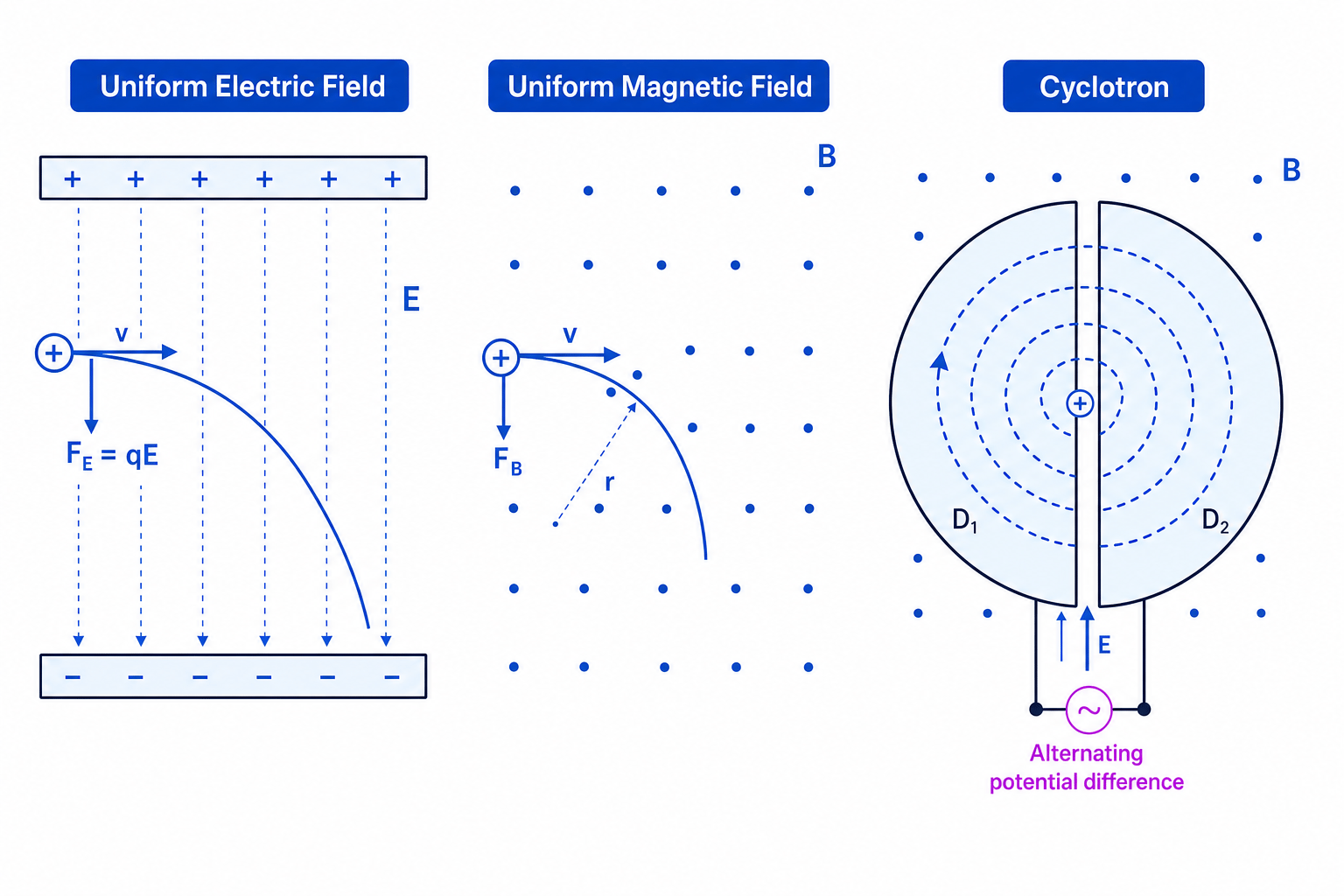
In a uniform electric field, a charged particle experiences:
F=qEF = qEF=qESo its acceleration is:
a=qEma = \frac{qE}{m}a=mqEIf the ion enters horizontally, the horizontal velocity stays constant, while the vertical motion is accelerated. The path is parabolic.
In a magnetic field, the force is perpendicular to the velocity. If the velocity is perpendicular to the field, the path is circular.
Deflection in a uniform electric field
A positive ion of charge 3.2×10⁻¹⁹ C3.2 \times 10^{-19}\ \text{C}3.2×10⁻¹⁹ C and mass 6.6×10⁻²⁷ kg6.6 \times 10^{-27}\ \text{kg}6.6×10⁻²⁷ kg enters a uniform electric field of strength 1.5×10⁴ N C−11.5 \times 10^4\ \text{N C}^{-1}1.5×10⁴ N C−1. Its horizontal speed is 2.0×10⁵ m s−12.0 \times 10^5\ \text{m s}^{-1}2.0×10⁵ m s−1 and the plates are 5.0 cm long. Find the vertical deflection while between the plates.
-
Calculate the electric force and acceleration:
a=qEm=3.2×10−19 C×1.5×104 N C−16.6×10⁻²⁷ kg=7.3×10¹¹ m s−2a = \frac{qE}{m} = \frac{3.2 \times 10^{-19}\ \text{C} \times 1.5 \times 10^4\ \text{N C}^{-1}}{6.6 \times 10^{-27}\ \text{kg}} = 7.3 \times 10^{11}\ \text{m s}^{-2}a=mqE=6.6×10⁻²⁷ kg3.2×10−19 C×1.5×104 N C−1=7.3×10¹¹ m s−2 -
Find the time in the plates using horizontal motion:
t=0.050 m2.0×105 m s−1=2.5×10⁻⁷ st = \frac{0.050\ \text{m}}{2.0 \times 10^5\ \text{m s}^{-1}} = 2.5 \times 10^{-7}\ \text{s}t=2.0×10⁵ m s−10.050 m=2.5×10⁻⁷ s -
Use vertical constant-acceleration motion, starting with zero vertical velocity:
s=12at2=12×7.3×1011 m s−2×(2.5×10−7 s)2s = \frac{1}{2}at^2 = \frac{1}{2} \times 7.3 \times 10^{11}\ \text{m s}^{-2} \times \left(2.5 \times 10^{-7}\ \text{s}\right)^2s=21at2=21×7.3×1011 m s−2×(2.5×10−7 s)2 -
Calculate:
s=2.3×10⁻² ms = 2.3 \times 10^{-2}\ \text{m}s=2.3×10⁻² m
Linear accelerators, cyclotrons and synchrotrons
A linear accelerator accelerates charged particles in a straight line using electric fields. Alternating voltages are timed so the particle is repeatedly accelerated in the correct direction.
A cyclotron uses:
- a magnetic field to bend particles in semicircles;
- an alternating potential difference to accelerate them across the gap between the two D-shaped electrodes;
- increasing radius as speed increases, since r=mv/(Bq)r = mv/(Bq)r=mv/(Bq).
A synchrotron keeps particles moving in a fixed circular ring. As the particles gain energy and momentum, the magnetic field is increased to keep the radius constant. Radio-frequency electric fields accelerate the particles at cavities around the ring.
These machines are important in research and medicine, but they also raise practical questions about cost, radiation shielding, and safe operation.
In the exam
- Start every magnetic-force question by checking whether the angle is 90 degrees; if not, keep the sinθ\sin\thetasinθ term.
- For direction questions, state whether you are using conventional current or a moving positive charge; reverse the direction for electrons.
- For practical questions, link the graph gradient to the equation, for example gradient of FFF against III is BlBlBl when the wire is perpendicular to the field.
Check yourself
- Why does a magnetic field change the direction of a charged particle but not its speed?
- How would you use a graph of force against current to find magnetic flux density?
- Why do parallel currents in the same direction attract?
