

What you'll learn
- How current and potential difference behave in series and parallel circuits.
- How to combine resistors and calculate currents and voltages in mixed circuits.
- How potential dividers work, including with LDRs and thermistors.
- What emf and internal resistance mean, and how to determine internal resistance experimentally.
Prerequisites: the language of circuits
A D.C. circuit is a circuit supplied by direct current, meaning the current flows in one direction around the circuit. In this topic, you will usually treat the current as steady once the switch is closed.
Current, potential difference and resistance
- Current III is the rate of flow of charge: I=ΔQΔtI = \frac{\Delta Q}{\Delta t}I=ΔtΔQ. Its unit is the ampere (A).
- Potential difference VVV is the energy transferred per unit charge between two points: V=WQV = \frac{W}{Q}V=QW. Its unit is the volt (V).
- Resistance RRR measures how strongly a component opposes current: V=IRV = IRV=IR. Its unit is the ohm (Ω).
In circuit calculations, assume connecting wires have negligible resistance unless told otherwise. Ammeters are placed in series; voltmeters are placed in parallel with the component or source being measured.
Series and parallel: the conservation laws
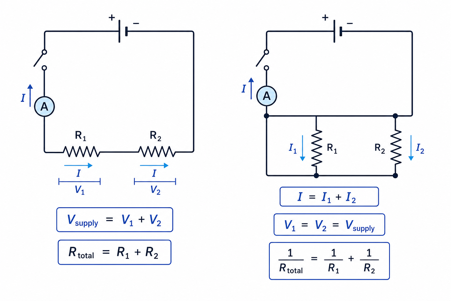
A series circuit has one path for charge. The same current passes through every component.
A parallel circuit has branches. At a junction, charge splits between branches and then recombines.
Why the rules work
- In a parallel circuit, the current from the source equals the sum of the currents in the branches because charge is conserved.
- In a series circuit, the sum of the potential differences across the components equals the supply potential difference because energy is conserved.
- Components in parallel have the same potential difference across them because each branch is connected across the same two points.
So for branches in parallel:
I=I1+I2+I3+⋯I = I_1 + I_2 + I_3 + \cdotsI=I1+I2+I3+⋯For components in series:
Vsupply=V1+V2+V3+⋯V_{\text{supply}} = V_1 + V_2 + V_3 + \cdotsVsupply=V1+V2+V3+⋯For components in parallel:
V1=V2=VsupplyV_1 = V_2 = V_{\text{supply}}V1=V2=VsupplyCombining resistors
For resistors in series, resistances add:
R=R1+R2+R3+⋯R = R_1 + R_2 + R_3 + \cdotsR=R1+R2+R3+⋯For resistors in parallel, reciprocals add:
1R=1R1+1R2+1R3+⋯\frac{1}{R} = \frac{1}{R_1} + \frac{1}{R_2} + \frac{1}{R_3} + \cdotsR1=R11+R21+R31+⋯Parallel resistance sanity check
The combined resistance of resistors in parallel is always less than the smallest individual resistance. If your answer is bigger, you have probably added the resistances as if they were in series.
Finding currents in a mixed resistor circuit
A 12.0 V supply is connected to a 4.0 Ω resistor in series with a parallel combination of 6.0 Ω and 12.0 Ω resistors. Find the total current and the current in each parallel branch.
-
Combine the parallel pair first:
1Rparallel=16.0 Ω+112.0 Ω=0.250 Ω−1\frac{1}{R_{\text{parallel}}}=\frac{1}{6.0\,\Omega}+\frac{1}{12.0\,\Omega}=0.250\,\Omega^{-1}Rparallel1=6.0Ω1+12.0Ω1=0.250Ω−1so
Rparallel=4.0 ΩR_{\text{parallel}}=4.0\,\OmegaRparallel=4.0Ω -
Add the series resistor:
Rtotal=4.0 Ω+4.0 Ω=8.0 ΩR_{\text{total}}=4.0\,\Omega+4.0\,\Omega=8.0\,\OmegaRtotal=4.0Ω+4.0Ω=8.0Ω -
Use V=IRV = IRV=IR to find the current from the supply:
I=VR=12.0 V8.0 Ω=1.50 AI=\frac{V}{R}=\frac{12.0\,\text{V}}{8.0\,\Omega}=1.50\,\text{A}I=RV=8.0Ω12.0V=1.50A -
The 4.0 Ω series resistor has potential difference:
V=IR=1.50 A×4.0 Ω=6.0 VV=IR=1.50\,\text{A}\times 4.0\,\Omega=6.0\,\text{V}V=IR=1.50A×4.0Ω=6.0Vso the parallel section also has 6.0 V across it.
-
Find the branch currents:
I6.0=6.0 V6.0 Ω=1.00 AI_{6.0}=\frac{6.0\,\text{V}}{6.0\,\Omega}=1.00\,\text{A}I6.0=6.0Ω6.0V=1.00A I12.0=6.0 V12.0 Ω=0.500 AI_{12.0}=\frac{6.0\,\text{V}}{12.0\,\Omega}=0.500\,\text{A}I12.0=12.0Ω6.0V=0.500AThe branch currents add to 1.50 A, matching conservation of charge.
Using the supply voltage on every component
Only components in parallel with the supply have the full supply potential difference across them. In series sections, the supply potential difference is shared between components.
Potential dividers
A potential divider uses resistors in series to produce a chosen fraction of the supply potential difference. The output is usually taken across one resistor.
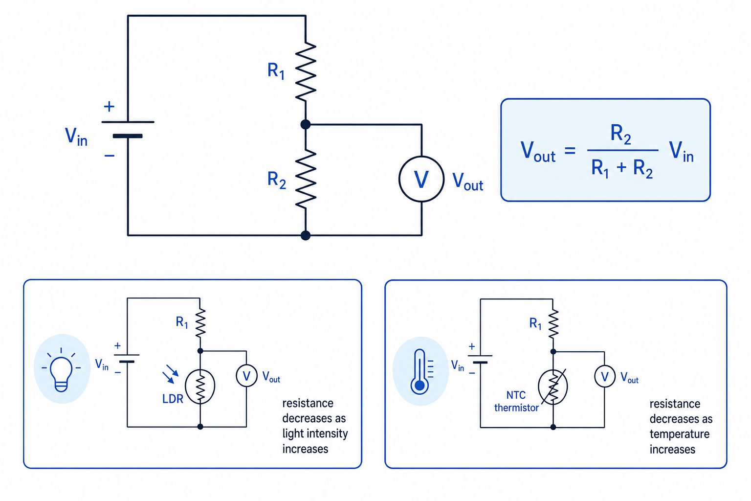
For two resistors in series, with the output across R2R_2R2:
Vout=R2R1+R2VinV_{\text{out}}=\frac{R_2}{R_1+R_2}V_{\text{in}}Vout=R1+R2R2VinThis works because the same current passes through both resistors, so the larger resistance gets the larger share of the potential difference.
An LDR, or light-dependent resistor, has resistance that decreases as light intensity increases. An NTC thermistor has resistance that decreases as temperature increases.
Sensor position matters
If the sensor is the lower resistor and VoutV_{\text{out}}Vout is measured across it, then decreasing the sensor resistance decreases VoutV_{\text{out}}Vout. If the sensor is the upper resistor, the trend reverses.
Calculating a potential divider output
A 9.0 V supply is connected across a potential divider. The upper resistor is 2.2 kΩ and the lower resistor is an LDR. The output is measured across the LDR. The LDR resistance is 1.0 kΩ in bright light and 10 kΩ in the dark. Find the output voltage in each case.
-
Use the divider equation with the LDR as R2R_2R2:
Vout=R2R1+R2VinV_{\text{out}}=\frac{R_2}{R_1+R_2}V_{\text{in}}Vout=R1+R2R2Vin -
In bright light:
Vout=1.0 kΩ2.2 kΩ+1.0 kΩ×9.0 V=2.8 VV_{\text{out}}=\frac{1.0\,\text{k}\Omega}{2.2\,\text{k}\Omega+1.0\,\text{k}\Omega}\times 9.0\,\text{V}=2.8\,\text{V}Vout=2.2kΩ+1.0kΩ1.0kΩ×9.0V=2.8V -
In the dark:
Vout=10 kΩ2.2 kΩ+10 kΩ×9.0 V=7.4 VV_{\text{out}}=\frac{10\,\text{k}\Omega}{2.2\,\text{k}\Omega+10\,\text{k}\Omega}\times 9.0\,\text{V}=7.4\,\text{V}Vout=2.2kΩ+10kΩ10kΩ×9.0V=7.4V -
The output is larger in the dark because the LDR resistance is larger, so it takes a larger fraction of the supply potential difference.
Loaded potential dividers
The simple divider formula assumes the output is measured by a very high-resistance voltmeter or device, so almost no current is drawn from the output. If a low-resistance load is connected, it is effectively in parallel with R2R_2R2 and changes the divider ratio.
Emf and internal resistance
The emf EEE of a source is the energy transferred by the source per unit charge. Its unit is the volt (V), the same as potential difference.
Emf
The emf EEE of a source is the energy supplied by the source to each coulomb of charge passing through it. When no current is drawn, the terminal potential difference is equal to the emf.
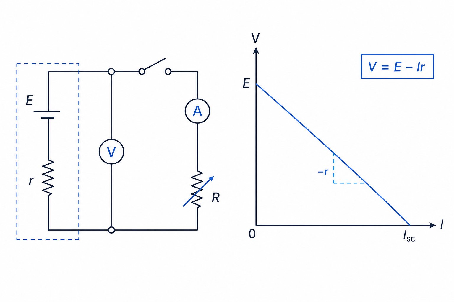
Real cells are not ideal. They have internal resistance rrr, meaning some energy is transferred inside the cell itself, usually as thermal energy. The potential difference available across the external terminals is called the terminal potential difference VVV.
The Eduqas equation is:
V=E−IrV = E - IrV=E−IrHere, IrIrIr is called the lost volts: the potential difference across the internal resistance.
Using internal resistance with cells in series
Two identical cells are connected in series, each with emf 1.50 V and internal resistance 0.30 Ω. They supply two external resistors, 5.0 Ω and 10.0 Ω, connected in series. Find the current and the terminal potential difference of the battery.
-
Add the emfs and internal resistances because the cells are in series and facing the same direction:
Etotal=1.50 V+1.50 V=3.00 VE_{\text{total}}=1.50\,\text{V}+1.50\,\text{V}=3.00\,\text{V}Etotal=1.50V+1.50V=3.00V rtotal=0.30 Ω+0.30 Ω=0.60 Ωr_{\text{total}}=0.30\,\Omega+0.30\,\Omega=0.60\,\Omegartotal=0.30Ω+0.30Ω=0.60Ω -
Add the external series resistance:
Rexternal=5.0 Ω+10.0 Ω=15.0 ΩR_{\text{external}}=5.0\,\Omega+10.0\,\Omega=15.0\,\OmegaRexternal=5.0Ω+10.0Ω=15.0Ω -
Use the total circuit resistance, including internal resistance:
I=EtotalRexternal+rtotal=3.00 V15.0 Ω+0.60 Ω=0.192 AI=\frac{E_{\text{total}}}{R_{\text{external}}+r_{\text{total}}} =\frac{3.00\,\text{V}}{15.0\,\Omega+0.60\,\Omega} =0.192\,\text{A}I=Rexternal+rtotalEtotal=15.0Ω+0.60Ω3.00V=0.192A -
Find the terminal potential difference:
V=E−Ir=3.00 V−(0.192 A×0.60 Ω)=2.88 VV=E-Ir=3.00\,\text{V}-(0.192\,\text{A}\times 0.60\,\Omega)=2.88\,\text{V}V=E−Ir=3.00V−(0.192A×0.60Ω)=2.88V -
Check against the external circuit:
V=IRexternal=0.192 A×15.0 Ω=2.88 VV=IR_{\text{external}}=0.192\,\text{A}\times 15.0\,\Omega=2.88\,\text{V}V=IRexternal=0.192A×15.0Ω=2.88V
Specified practical: determining internal resistance
Set up a cell connected to a switch, ammeter and variable resistor in series. Place a voltmeter across the cell terminals. Change the resistance to get different currents, and record the current III and terminal potential difference VVV each time.
Plot VVV on the vertical axis against III on the horizontal axis. Compare:
V=E−IrV = E - IrV=E−Irwith the straight-line form:
y=mx+cy = mx + cy=mx+cSo the y-intercept gives EEE, and the gradient gives −r-r−r.
Finding internal resistance from a graph
A graph of terminal potential difference against current has a y-intercept of 1.54 V. Two points on the best-fit line are (0.20 A, 1.42 V) and (1.00 A, 0.94 V). Find the emf and internal resistance.
-
Read the emf from the y-intercept:
E=1.54 VE=1.54\,\text{V}E=1.54V -
Calculate the gradient of the graph:
gradient=0.94 V−1.42 V1.00 A−0.20 A=−0.48 V0.80 A=−0.60 Ω\text{gradient}=\frac{0.94\,\text{V}-1.42\,\text{V}}{1.00\,\text{A}-0.20\,\text{A}} =\frac{-0.48\,\text{V}}{0.80\,\text{A}} =-0.60\,\Omegagradient=1.00A−0.20A0.94V−1.42V=0.80A−0.48V=−0.60Ω -
Since the gradient is −r-r−r:
r=0.60 Ωr=0.60\,\Omegar=0.60Ω
For good practical technique, switch off between readings to reduce heating, avoid very low load resistances that could cause large currents, and choose meter ranges that give sensible precision. Record meter resolution, repeat readings where possible, and use error bars or steepest and shallowest acceptable gradients to estimate uncertainty in rrr.
In the exam
- Mark junctions and loops first: use current conservation at junctions and energy conservation around loops.
- Reduce resistor networks in stages, starting with obvious series or parallel groups.
- In potential dividers, identify exactly which resistor VoutV_{\text{out}}Vout is measured across before substituting.
- For internal resistance graphs, plot VVV against III: intercept is EEE, gradient is −r-r−r.
Check yourself
- Why does the current split in a parallel circuit but stay the same in a series circuit?
- If an LDR is the lower resistor in a potential divider, what happens to VoutV_{\text{out}}Vout when light intensity increases?
- On a graph of terminal potential difference against current, how would you find the internal resistance?
