

What you'll learn
- What a capacitor is and how it stores energy by separating charge.
- How to use C=QVC = \frac{Q}{V}C=VQ, C=ϵ0AdC = \frac{\epsilon_0 A}{d}C=dϵ0A, E=VdE = \frac{V}{d}E=dV and U=12QVU = \frac{1}{2}QVU=21QV.
- How capacitors combine in series and parallel.
- How capacitors charge and discharge exponentially through a resistor, including how to determine the time constant experimentally.
Before we start: charge, p.d. and fields
Electric charge is measured in coulombs, C. A potential difference, often called p.d. or voltage, is energy transferred per unit charge and is measured in volts, V. An electric field is a region where a charge experiences a force.
Capacitance brings these ideas together: a capacitor stores separated charge, has a p.d. across it, and stores energy in the electric field between its plates.
The simple parallel plate capacitor
A simple parallel plate capacitor consists of two equal parallel metal plates separated by a vacuum or air. In many A-Level questions, air is treated as approximately the same as a vacuum.
When a capacitor is connected to a direct current supply, electrons are transferred from one plate to the other. One plate becomes negatively charged and the other becomes positively charged. The plates carry equal and opposite charges, so the net charge of the whole capacitor is zero.
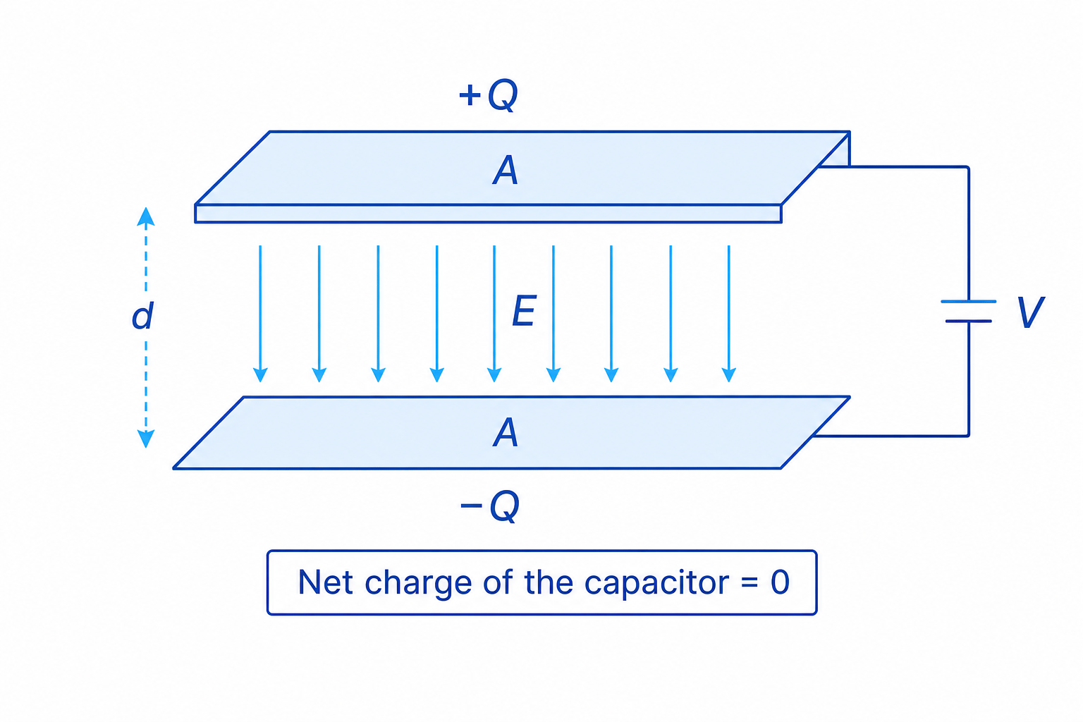
What a capacitor stores
A capacitor does not store net charge overall; it stores separated charge and therefore energy in the electric field between its plates.
Treating Q as the net charge
In capacitor equations, QQQ means the magnitude of the charge on one plate, not the total charge of the two plates added together. The total net charge is zero.
Capacitance
Capacitance tells you how much charge a capacitor stores for each volt of potential difference across it.
Capacitance
The capacitance, CCC, of a capacitor is defined by
C=QVC = \frac{Q}{V}C=VQwhere QQQ is the magnitude of the charge on one plate and VVV is the potential difference across the capacitor. The unit is the farad, F, where 1 F=1 C V−11\ \text{F} = 1\ \text{C V}^{-1}1 F=1 C V−1.
One farad is very large, so practical capacitors are often in microfarads, nanofarads or picofarads.
Finding the charge stored
A 470 µF capacitor is connected across a 12.0 V supply. Find the charge on each plate.
-
Convert the capacitance into farads:
C=470×10−6 FC = 470 \times 10^{-6}\ \text{F}C=470×10−6 F -
Rearrange C=QVC = \frac{Q}{V}C=VQ to make QQQ the subject, then substitute:
Q=CV=(470×10−6 F)(12.0 V)Q = CV = \left(470 \times 10^{-6}\ \text{F}\right)\left(12.0\ \text{V}\right)Q=CV=(470×10−6 F)(12.0 V) -
Calculate the charge:
Q=5.64×10⁻³ CQ = 5.64 \times 10^{-3}\ \text{C}Q=5.64×10⁻³ CSo one plate has charge +5.64×10⁻³ C+5.64 \times 10^{-3}\ \text{C}+5.64×10⁻³ C and the other has charge −5.64×10⁻³ C-5.64 \times 10^{-3}\ \text{C}−5.64×10⁻³ C.
What affects the capacitance of parallel plates?
For a parallel plate capacitor with no dielectric, the capacitance is
C=ϵ0AdC = \frac{\epsilon_0 A}{d}C=dϵ0Awhere ϵ0\epsilon_0ϵ0 is the permittivity of free space, AAA is the area of overlap of one plate, and ddd is the plate separation.
This equation says that capacitance increases if the plates have a larger area, and decreases if the plates are moved further apart.
Dielectric
A dielectric is an insulating material placed between the plates of a capacitor. It increases the capacitance compared with the same capacitor with a vacuum between the plates.
A dielectric becomes polarised in the electric field. This reduces the p.d. for a given stored charge, so the capacitor can store more charge for the same p.d.; in other words, its capacitance increases.
When C = epsilon nought A over d applies
Use C=ϵ0AdC = \frac{\epsilon_0 A}{d}C=dϵ0A only for an ideal parallel plate capacitor with vacuum or air between the plates and no dielectric material inserted.
Electric field between parallel plates
Away from the plate edges, the electric field between parallel plates is uniform. Uniform means it has the same magnitude and direction at every point in the region.
For plate separation ddd and p.d. VVV,
E=VdE = \frac{V}{d}E=dVElectric field strength may be measured in volts per metre, V m⁻¹, or newtons per coulomb, N C⁻¹.
Parallel plate capacitance and field strength
Two parallel plates each have overlapping area 2.0×10⁻³ m22.0 \times 10^{-3}\ \text{m}^22.0×10⁻³ m2 and are separated by 0.50 mm of air. A p.d. of 60 V is applied. Find the capacitance and the electric field strength.
-
Convert the separation into metres:
d=0.50 mm=5.0×10⁻⁴ md = 0.50\ \text{mm} = 5.0 \times 10^{-4}\ \text{m}d=0.50 mm=5.0×10⁻⁴ m -
Use C=ϵ0AdC = \frac{\epsilon_0 A}{d}C=dϵ0A with ϵ0=8.85×10⁻¹² F m−1\epsilon_0 = 8.85 \times 10^{-12}\ \text{F m}^{-1}ϵ0=8.85×10⁻¹² F m−1:
C=(8.85×10⁻¹² F m−1)(2.0×10⁻³ m2)5.0×10⁻⁴ m=3.54×10⁻¹¹ FC = \frac{\left(8.85 \times 10^{-12}\ \text{F m}^{-1}\right)\left(2.0 \times 10^{-3}\ \text{m}^2\right)}{5.0 \times 10^{-4}\ \text{m}} = 3.54 \times 10^{-11}\ \text{F}C=5.0×10⁻⁴ m(8.85×10⁻¹² F m−1)(2.0×10⁻³ m2)=3.54×10⁻¹¹ F -
Use E=VdE = \frac{V}{d}E=dV for the uniform field:
E=60 V5.0×10−4 m=1.2×10⁵ V m−1E = \frac{60\ \text{V}}{5.0 \times 10^{-4}\ \text{m}} = 1.2 \times 10^{5}\ \text{V m}^{-1}E=5.0×10⁻⁴ m60 V=1.2×10⁵ V m−1
Energy stored in a capacitor
As a capacitor charges, work is done moving charge from one plate to the other against the growing electric field. This work becomes energy stored in the capacitor.
The energy stored is
U=12QVU = \frac{1}{2}QVU=21QVUsing Q=CVQ = CVQ=CV, you can also write
U=12CV2U = \frac{1}{2}CV^2U=21CV2and
U=Q22CU = \frac{Q^2}{2C}U=2CQ2The factor of one half appears because the p.d. is not constant while the capacitor charges; it rises from zero to its final value.
Calculating stored energy
A capacitor has charge 3.0×10⁻³ C3.0 \times 10^{-3}\ \text{C}3.0×10⁻³ C when the p.d. across it is 8.0 V. Calculate the energy stored.
-
Choose the equation using the given quantities:
U=12QVU = \frac{1}{2}QVU=21QV -
Substitute the charge and p.d.:
U=12(3.0×10⁻³ C)(8.0 V)U = \frac{1}{2}\left(3.0 \times 10^{-3}\ \text{C}\right)\left(8.0\ \text{V}\right)U=21(3.0×10⁻³ C)(8.0 V) -
Calculate the energy:
U=1.2×10⁻² JU = 1.2 \times 10^{-2}\ \text{J}U=1.2×10⁻² J
Specified practical: investigating energy stored
One way to investigate stored energy is to charge a capacitor to a known p.d., then discharge it through a known resistor while measuring the resistor p.d. with a data logger. Use I=VRRI = \frac{V_R}{R}I=RVR and P=I2RP = I^2RP=I2R or P=VR2RP = \frac{V_R^2}{R}P=RVR2, then find the area under the power-time graph. That area is the energy transferred from the capacitor.
You can repeat for different initial voltages. Since U=12CV2U = \frac{1}{2}CV^2U=21CV2, a graph of UUU against V2V^2V2 should be a straight line with gradient C2\frac{C}{2}2C.
Capacitors in parallel and series
Capacitors can be combined into a single equivalent capacitance.
In parallel, each capacitor has the same p.d. across it, and the charges add:
C=C1+C2+C3+⋯C = C_1 + C_2 + C_3 + \cdotsC=C1+C2+C3+⋯In series, each capacitor stores the same charge, and the p.d.s add:
1C=1C1+1C2+1C3+⋯\frac{1}{C} = \frac{1}{C_1} + \frac{1}{C_2} + \frac{1}{C_3} + \cdotsC1=C11+C21+C31+⋯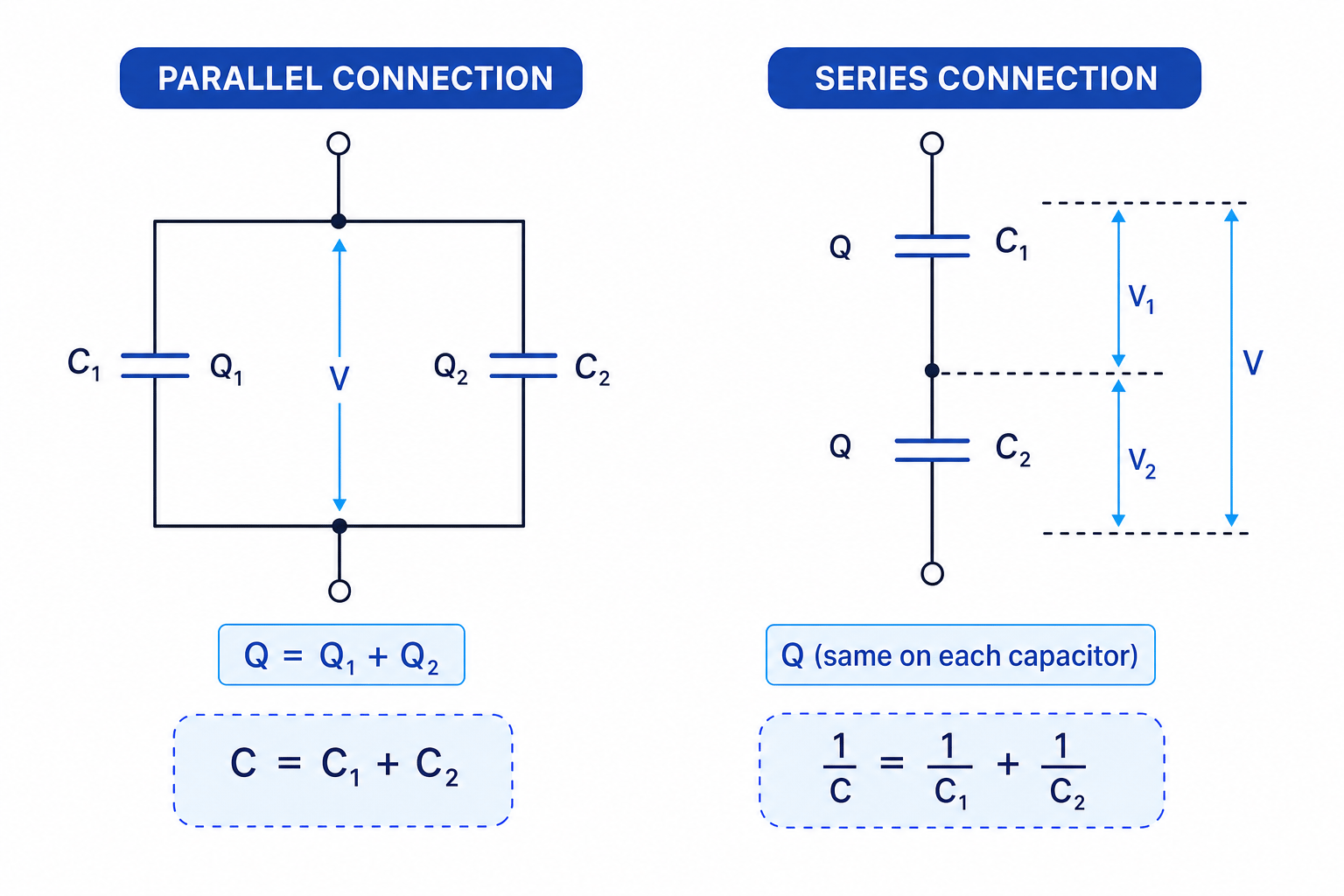
Combining capacitors
A 3.0 µF capacitor and a 6.0 µF capacitor are connected to a 12 V supply. Compare the equivalent capacitance and stored charge for parallel and series connections.
-
For parallel capacitors, add the capacitances:
C=3.0 μF+6.0 μF=9.0 μFC = 3.0\ \mu\text{F} + 6.0\ \mu\text{F} = 9.0\ \mu\text{F}C=3.0 μF+6.0 μF=9.0 μFThe total charge supplied is
Q=CV=(9.0×10⁻⁶ F)(12 V)=1.08×10⁻⁴ CQ = CV = \left(9.0 \times 10^{-6}\ \text{F}\right)\left(12\ \text{V}\right) = 1.08 \times 10^{-4}\ \text{C}Q=CV=(9.0×10⁻⁶ F)(12 V)=1.08×10⁻⁴ C -
For series capacitors, add reciprocals:
1C=13.0 μF+16.0 μF=12.0 μF\frac{1}{C} = \frac{1}{3.0\ \mu\text{F}} + \frac{1}{6.0\ \mu\text{F}} = \frac{1}{2.0\ \mu\text{F}}C1=3.0 μF1+6.0 μF1=2.0 μF1so
C=2.0 μFC = 2.0\ \mu\text{F}C=2.0 μF -
In series, the same charge is stored on each capacitor:
Q=CV=(2.0×10⁻⁶ F)(12 V)=2.4×10⁻⁵ CQ = CV = \left(2.0 \times 10^{-6}\ \text{F}\right)\left(12\ \text{V}\right) = 2.4 \times 10^{-5}\ \text{C}Q=CV=(2.0×10⁻⁶ F)(12 V)=2.4×10⁻⁵ C
Swapping the series and parallel rules
Capacitors behave opposite to resistors for the equivalent value: parallel capacitance adds directly, while series capacitance is found by adding reciprocals.
Charging and discharging through a resistor
When a capacitor charges through a resistor, the current is initially large because the capacitor p.d. is zero. As charge builds up, the capacitor p.d. increases, so the resistor p.d. and current decrease. The charge approaches a maximum value gradually.
When a charged capacitor discharges through a resistor, the capacitor drives a current through the resistor. The charge, p.d. and current all decrease exponentially.

For charging from uncharged:
Q=Q0(1−e−tRC)Q = Q_0 \left( 1 - e^{-\frac{t}{RC}} \right)Q=Q0(1−e−RCt)Here Q0Q_0Q0 is the final charge after a long time.
For discharging from an initial charge:
Q=Q0e−tRCQ = Q_0 e^{-\frac{t}{RC}}Q=Q0e−RCtHere Q0Q_0Q0 is the charge at the start of the discharge.
The quantity RCRCRC is the time constant. It is measured in seconds. After one time constant, a charging capacitor has reached about 63% of its final charge, while a discharging capacitor has fallen to about 37% of its initial charge.
Using the discharge equation
A 100 µF capacitor is charged to 9.0 V, then discharged through a 220 kΩ resistor. Find the time for the p.d. to fall to 2.0 V.
-
Calculate the time constant:
RC=(220×103 Ω)(100×10−6 F)=22 sRC = \left(220 \times 10^3\ \Omega\right)\left(100 \times 10^{-6}\ \text{F}\right) = 22\ \text{s}RC=(220×103 Ω)(100×10−6 F)=22 s -
Since Q=CVQ = CVQ=CV, the voltage ratio equals the charge ratio:
VV0=e−tRC\frac{V}{V_0} = e^{-\frac{t}{RC}}V0V=e−RCtso
2.09.0=e−t22 s\frac{2.0}{9.0} = e^{-\frac{t}{22\ \text{s}}}9.02.0=e−22 st -
Take natural logs and solve for ttt:
t=−(22 s)ln(2.09.0)=33 st = -\left(22\ \text{s}\right)\ln\left(\frac{2.0}{9.0}\right) = 33\ \text{s}t=−(22 s)ln(9.02.0)=33 s
Specified practical: determining the time constant
Use a DC supply, resistor, capacitor, switch and voltmeter or data logger. Electrolytic capacitors are polarised, so connect the positive terminal correctly and do not exceed the rated voltage.
For a simple graph method, record the capacitor p.d. against time. On charging, the time constant is the time to reach about 63% of the final p.d. On discharging, it is the time to fall to about 37% of the initial p.d.
For a more accurate straight-line method, discharge the capacitor and plot lnV\ln VlnV against ttt. Since
lnV=lnV0−tRC\ln V = \ln V_0 - \frac{t}{RC}lnV=lnV0−RCtthe gradient is −1RC-\frac{1}{RC}−RC1, so
RC=−1gradientRC = -\frac{1}{\text{gradient}}RC=−gradient1Improving RC practical data
Choose RRR and CCC so the time constant is several seconds, use a data logger to reduce reaction-time uncertainty, repeat runs and average, and fully discharge the capacitor before each repeat.
Capacitor safety
Large capacitors can remain charged after the supply is switched off. Discharge them safely through a resistor before handling or reconnecting the circuit.
Where capacitors show up
Capacitors are used in time-delay circuits because the p.d. across them changes gradually. Strong electric fields and charge separation are also important in devices such as electrostatic precipitators and photocopiers, where charged particles are moved or deposited using electric forces.
In the exam
- Check whether the question is about one plate charge QQQ, not net charge; for a capacitor the net charge is zero.
- Convert prefixes carefully before calculating: µF means 10−6 F10^{-6}\ \text{F}10−6 F, nF means 10−9 F10^{-9}\ \text{F}10−9 F and pF means 10−12 F10^{-12}\ \text{F}10−12 F.
- For RC questions, identify whether the capacitor is charging or discharging before choosing the exponential equation.
Check yourself
- Why does a capacitor have zero net charge even when it is storing energy?
- What happens to the capacitance of a parallel plate capacitor if the plate separation is doubled?
- How would you use a graph of lnV\ln VlnV against time to find the time constant during discharge?
