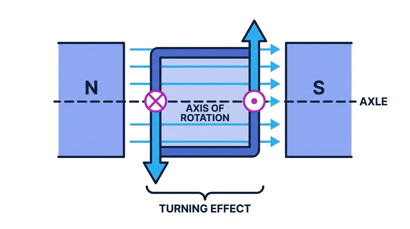
A coil in a magnetic field experiences a turning effect
- Each side of a current-carrying coil placed in a magnetic field feels the motor-effect force.
- The current runs in opposite directions along the two long sides, so the forces on those two sides act in opposite directions.
- One side is pushed up while the other is pushed down, and that pair of opposite forces produces a turning effect about the axle.
- The coil therefore rotates, and that rotation is the whole basis of an electric motor.
- The turning effect is greatest when the coil lies in the plane of the field, and falls to zero when it has turned to sit at right angles to it.
Three ways to increase the turning effect
- Increasing the number of turns on the coil increases it, because every turn adds its own pair of forces.
- Increasing the current increases it, since a larger current gives a larger force on each side.
- Using a stronger magnetic field increases it, for exactly the same reason.
- A fourth practical change is to make the coil wider, which increases the moment of each force about the axle.
- A real motor does all of these at once, with many turns wound on a soft-iron armature between strong curved magnets.
The split-ring commutator keeps the motor turning one way
- Left alone, the coil would swing round to the position where the turning effect is zero and then rock back and forth instead of spinning.
- What is needed is for the current in the coil to reverse every half turn, so that the forces keep pushing it round the same way.
- A split-ring commutator does exactly that: a metal ring cut into two halves, with each half joined to one end of the coil.
- Two carbon brushes from the supply press against the ring, staying still while the ring rotates underneath them.
- As the coil passes the vertical position, each brush slides from one half of the ring onto the other, so the connections swap over.
- The current through the coil therefore reverses at exactly the moment it needs to, and the coil carries on turning in one direction.
- The gaps in the split ring pass the brushes at the point where the turning effect is zero, so the coil coasts through that position on its own momentum.
- Contrast this with a generator's slip rings, which are complete rings and never swap the connections, so a generator's output stays alternating.
Turning the theory into a practical motor
- Swapping the supply connections makes the motor turn the other way, because it reverses the current in the coil.
- Turning the magnets round has the same effect, while reversing both together leaves the direction unchanged.
- A soft-iron armature inside the coil concentrates the field and so increases the force on each side.
- Curved pole pieces keep the field pointing across the coil throughout most of the turn, so the turning effect stays large for longer.
- Real motors use several coils set at different angles, so there is always one well placed to be pushed round and the motor never stalls.
Common Mistake
- A motor uses a split-ring commutator and a generator uses slip rings, so naming the wrong one loses the mark outright.
- The commutator reverses the current in the coil, not the direction of rotation, so do not describe it as reversing the motor.
- The forces on the two sides are in opposite directions; they do not cancel, because they act on opposite sides of the axle and so both turn the coil the same way.
- Reversing the current and the field together leaves the motor turning the same way, which is a favourite trap.
Exam technique
- Use Fleming's left-hand rule on one side at a time, then check that the two forces turn the coil the same way round.
- For a "how does the commutator work" question, the marks are for the connections swapping every half turn and for the current in the coil reversing as a result.
- If asked how to make the motor turn faster, give at least two of more turns, a larger current and a stronger field.
- Label a motor diagram fully: coil, magnet poles, axle, split-ring commutator and brushes.
Self review
- Why does a current-carrying coil in a magnetic field experience a turning effect?
- State three ways of increasing that turning effect.
- What is the job of the split-ring commutator?
- What are the brushes for, and what are they usually made of?
- Give two ways of making a d.c. motor turn in the opposite direction.