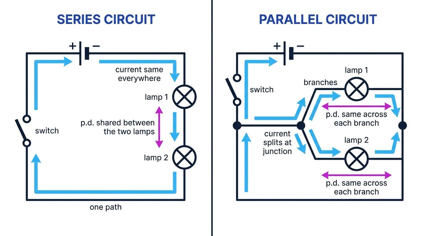
One path means one current, the same at every point
Definition
Series circuit
A circuit in which the components are joined one after another in a single loop, so the same current passes through every component.
- There are no junctions anywhere in a series circuit, so the charge has nowhere else it could go.
- Move an ammeter anywhere round the loop and it reads the same current: before the first lamp, between the two lamps, and after the second.
- Charge is not used up, only the energy it carries, which is why the current does not shrink as it passes through each component.
- Breaking the loop anywhere stops the current everywhere, so one blown lamp in a series string switches the whole string off.
- Adding another component increases the total resistance, so the current everywhere falls and each lamp in the string is dimmer.
Cells in series add their e.m.f.s
- Joining cells positive to negative in a line puts them in series, and their e.m.f.s add together.
- Three 1.5 V1.5\ \text{V}1.5 V cells in series therefore give a total e.m.f. of 1.5+1.5+1.5=4.5 V1.5 + 1.5 + 1.5 = 4.5\ \text{V}1.5+1.5+1.5=4.5 V.
- Turning one cell round makes its e.m.f. subtract, so two 1.5 V1.5\ \text{V}1.5 V cells facing each other give a total of 0 V0\ \text{V}0 V and nothing works.
- That is exactly what has happened when a torch stays dark with one battery in the wrong way round.
- Cells in series give a larger e.m.f. but do not last any longer, because every coulomb still has to pass through all of them.
Resistors in series simply add
- The combined resistance is the sum of the separate resistances, so R=R1+R2+R3R = R_1 + R_2 + R_3R=R1+R2+R3 and so on.
- They add because the charge has to pass through all of them one after another, meeting each obstruction in turn.
- The total is therefore always larger than the biggest single resistor in the chain, which is a quick check on any answer.
- Once you have the total, the current follows from I=VRI = \dfrac{V}{R}I=RV using the total e.m.f. and the total resistance.
- Because the current is the same everywhere, the p.d. across any one resistor is then V=IRV = IRV=IR using that resistor's own value.
Common Mistake
- The current does not get smaller as it goes through each component; what falls is the energy each coulomb still carries.
- Resistors in series always give a larger total, so an answer smaller than one of them means the parallel formula has been used by mistake.
- Cells only add if they all face the same way round, so check the symbols before adding the e.m.f.s.
- Do not use the supply p.d. to find the p.d. across one resistor; use V=IRV = IRV=IR with that resistor's own resistance.
Exam technique
- Work in a fixed order on series problems: total resistance first, then the current, then the individual p.d.s.
- State the sentence "the current is the same at all points in a series circuit" when a question gives you a reading at one point and asks for another.
- Check your p.d.s add up to the supply, because that is a free way to catch an arithmetic slip.
- If asked why the lamps dim when a third is added, name the increased total resistance and then the reduced current.
Self review
- What can you say about the current at different points in a series circuit?
- Four 1.5 V1.5\ \text{V}1.5 V cells are joined in series the same way round. State the total e.m.f.
- Calculate the combined resistance of a 5.0 Ω5.0\ \Omega5.0 Ω and a 7.0 Ω7.0\ \Omega7.0 Ω resistor in series.
- Why does the whole string go out when one lamp in a series circuit fails?
- A 9.0 V9.0\ \text{V}9.0 V battery drives a current through a 10 Ω10\ \Omega10 Ω and a 20 Ω20\ \Omega20 Ω resistor in series. Find the current.