A circuit diagram is a shared code for showing how components are joined
- A circuit diagram replaces a picture of the real apparatus with standard symbols joined by straight lines.
- The lines stand for connecting wire of negligible resistance, so their length and shape carry no meaning at all.
- Draw the wires as straight lines with right-angled corners and use a ruler, because a wobbly line can be misread as a resistor.
- Two wires that cross without a blob are not joined; a blob at the crossing means they are connected.
- Every component sits in a gap in the line, and the whole arrangement must form at least one complete loop before any current can flow.
Sources, switches and meters
- Cell: a long thin line for the positive terminal and a short thick line for the negative, supplying a fixed e.m.f.
- Battery: two or more cells joined in series, drawn as repeated cell symbols, giving a larger e.m.f.
- Power supply: a d.c. or a.c. source that can usually be set to a chosen voltage.
- Generator: a circle marked G, producing an e.m.f. from a rotating coil.
- Switch: a break in the line with a hinged arm, and opening it stops the current everywhere in that loop.
- Ammeter: a circle marked A, always drawn in series because it has to carry the current it measures.
- Voltmeter: a circle marked V, always drawn in parallel across the component being measured.
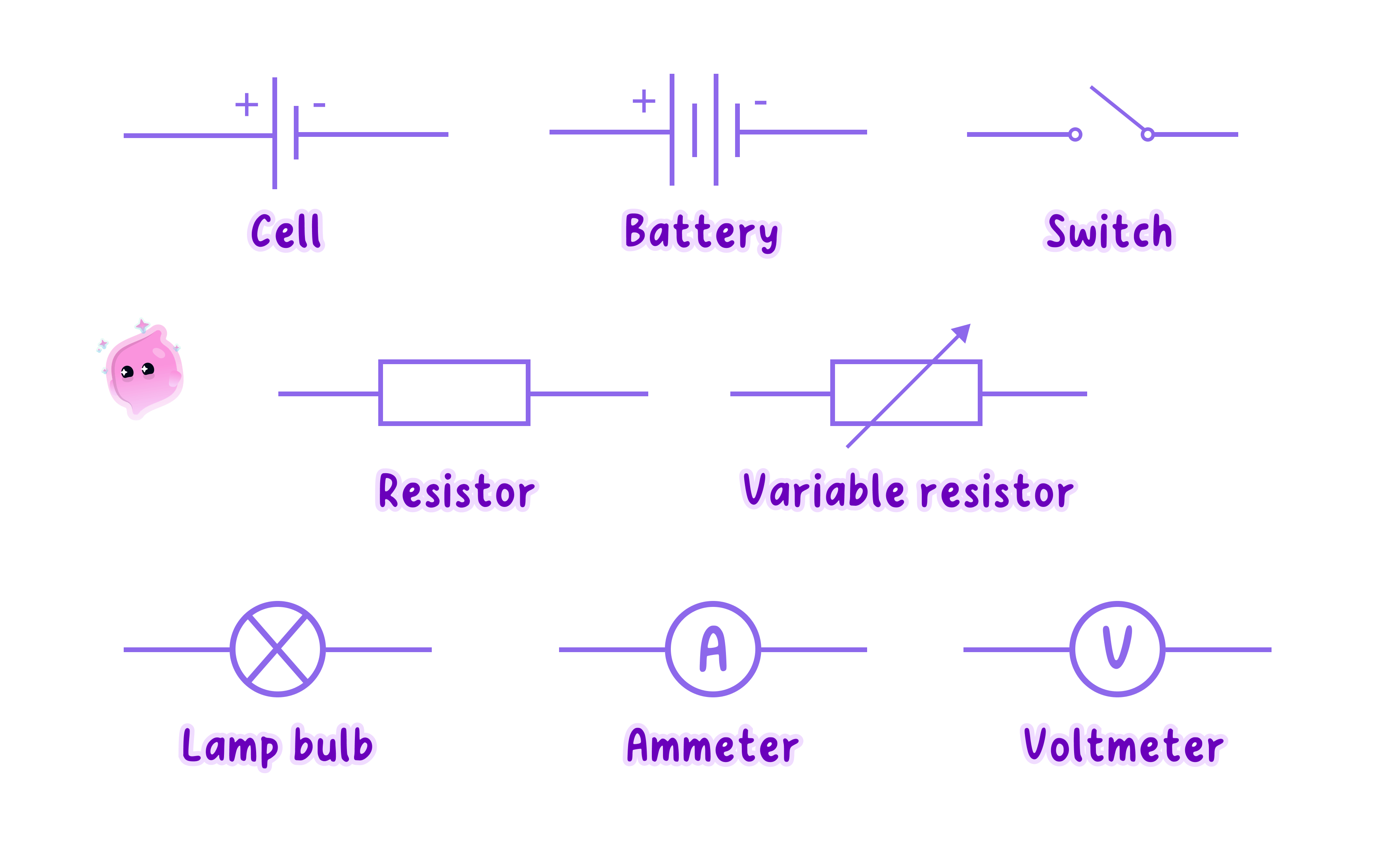
Resistive components and the things they drive
- Fixed resistor: a plain rectangle, limiting the current with a resistance that does not change.
- Variable resistor: a rectangle with an arrow through it, and moving the slider changes the resistance and so changes the current.
- Potential divider: two resistors in series across the supply, or one resistor with a sliding contact, used to tap off part of the supply voltage.
- Lamp: a circle with a cross, which glows and whose resistance rises as the filament heats up.
- Heater: a rectangle that turns almost all of the energy delivered to it into thermal energy.
- Motor: a circle marked M, which turns while a current flows through it.
- Bell: a dome-shaped symbol that rings for as long as a current flows.
- Fuse: a rectangle with a line through it, which melts and breaks the circuit if the current becomes too large.
- Relay: a coil that closes a switch in a second, separate circuit when a small current flows through it.
- Magnetising coil: a coil of wire that produces a magnetic field whenever a current passes through it.
- Transformer: two coils drawn either side of a core, changing an alternating voltage up or down.
Sensing components change their resistance when their surroundings change
- A thermistor is drawn as a resistor with a diagonal line across it, and the type you need has a resistance that falls as the temperature rises.
- Put one in a circuit and the current rises as it warms, which is how a thermostat or a fire alarm senses heat.
- A light-dependent resistor, or LDR, is drawn as a resistor inside a circle with two arrows pointing in towards it.
- Its resistance is high in the dark and low in bright light, so the current in its branch rises when light falls on it.
- An LDR is what switches a street lamp on at dusk and turns a phone screen brighter in sunlight.
Diodes and LEDs conduct in one direction only
- A diode is drawn as a triangle pointing at a bar, and it lets conventional current pass only in the direction the triangle points.
- In the reverse direction its resistance is enormous, so the current is effectively zero.
- That makes a diode the component used to turn a.c. into d.c., and to protect a circuit from a battery fitted the wrong way round.
- A light-emitting diode, or LED, uses the same symbol with two arrows pointing away from it, and it gives out light while conducting in the forward direction.
- An LED needs a series resistor to limit the current, because its own resistance drops very low once it starts conducting.
Common Mistake
- A crossing of two wires only counts as a connection if a blob is drawn at the junction.
- The thermistor you need has a resistance that falls as it gets hotter, so do not describe the opposite behaviour.
- Never draw an ammeter across a component or a voltmeter in series, because the placement is part of what the symbol means.
- A diode drawn the wrong way round changes the whole answer, so check which way the triangle points before using it.
Exam technique
- Draw with a ruler, keep the symbols a sensible size and leave the corners square, because a scruffy diagram loses marks it did not need to.
- Label every component you were asked to include, and mark the direction of the conventional current with an arrow.
- If asked what a component does, give its behaviour rather than its name, as in "its resistance falls when light shines on it".
- Trace the loop with a finger before you finish, since a diagram with an unnoticed gap in it earns nothing.
Self review
- Draw the symbols for a cell, a lamp, a fixed resistor and a voltmeter.
- What does a blob where two wires cross tell you?
- How does the resistance of a thermistor change as it gets hotter?
- How does the resistance of an LDR change as it gets darker?
- Describe what a diode does in each direction, and why an LED needs a series resistor.
