Series circuits
Definition
Series circuit
A circuit in which the components are connected one after another in a single loop, so there is only one path for the charge to flow through.
- In a series circuit, the components are joined end to end so that they form a single loop with the power supply.
- There is only one path around the circuit, so all of the charge that leaves the supply passes through every component in turn.
- The current is the same at every point in a series circuit, because charge is not used up by the components and cannot leave the loop anywhere.
- An ammeter placed before the first lamp, between two lamps or after the last lamp gives the same reading.
- The potential difference of the supply is shared between the components, so the potential differences across the components add up to the potential difference across the supply.
- For two components in series, this is written as Vsupply=V1+V2V_{\text{supply}} = V_1 + V_2Vsupply=V1+V2.
- The component with the larger resistance takes the larger share of the potential difference.
- In terms of energy, each coulomb of charge is given energy by the supply and then transfers part of that energy in each component it passes through.
- The energy transferred by each coulomb in all of the components adds up to the energy it was given by the supply.
- If one component is removed, breaks or is switched off, the single loop is broken and every component stops working.
- Old-style strings of festive lights were wired in series, so one failed bulb made the whole string go dark.
- One switch placed anywhere in a series circuit turns all of the components on or off together.
Parallel circuits
Definition
Parallel circuit
A circuit in which the components are connected in separate branches between the same two points, so there is more than one path for the charge to flow through.
Definition
Junction
A point in a circuit where a conducting path splits into two or more branches, or where branches join back together.
- In a parallel circuit, each component is placed on its own branch, and every branch is connected between the same two points of the circuit.
- The current from the supply splits at a junction, part of it flows along each branch, and the branch currents recombine at a second junction.
- The total current from the supply is equal to the sum of the branch currents, written Itotal=I1+I2I_{\text{total}} = I_1 + I_2Itotal=I1+I2 for two branches.
- A branch with a smaller resistance carries a larger current than a branch with a larger resistance.
- Each branch is connected directly across the supply, so the potential difference across every branch is the same and equal to the supply potential difference.
- In terms of energy, each coulomb of charge passes through only one branch, so it transfers all of the energy it was given by the supply in that branch.
- Each branch can be switched on and off independently, and a break in one branch does not stop charge flowing through the others.
- The lights and sockets in a house are wired in parallel, so every appliance receives the full mains potential difference and switching off the kettle does not switch off the fridge.
- Adding another identical lamp in series shares the supply potential difference between more lamps, so each lamp gets a smaller share and glows more dimly.
- Adding another identical lamp in parallel gives it the full supply potential difference, so it glows as brightly as the lamps already there, while the total current from the supply increases.
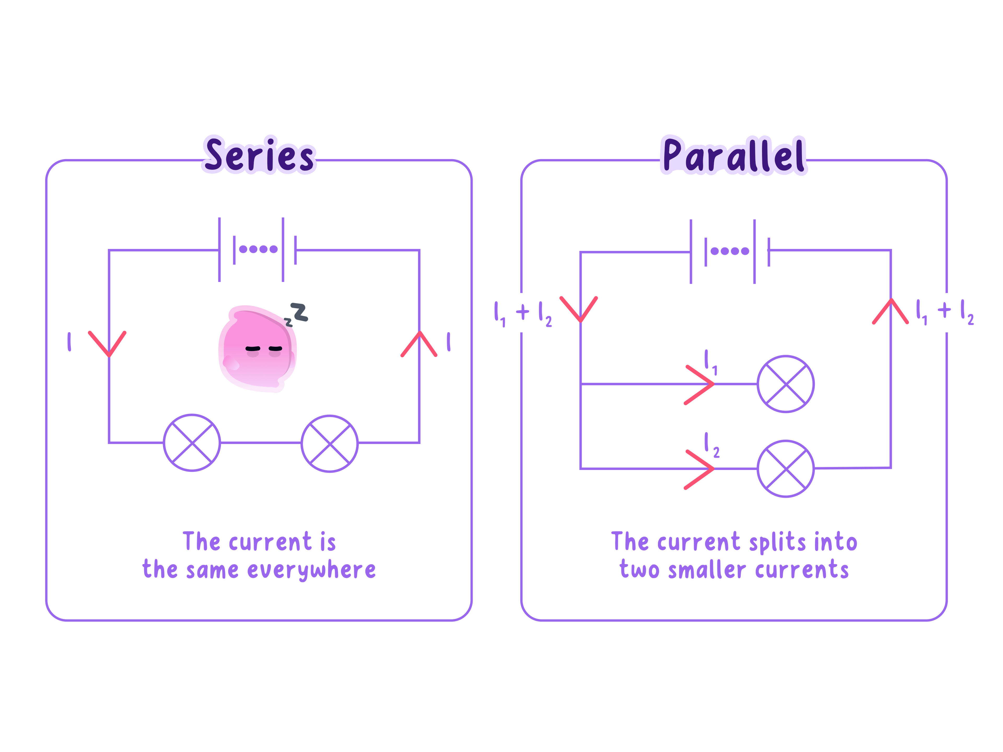
Comparing the two circuits
- Paths: a series circuit has one path for the charge, whereas a parallel circuit has a separate path through each branch.
- Current: the current is the same everywhere in a series circuit, whereas in a parallel circuit the branch currents add up to the total current.
- Potential difference: the supply potential difference is shared between series components, whereas each parallel branch has the full supply potential difference across it.
- Energy: each coulomb transfers some of its energy in every series component, whereas it transfers all of its energy in the one parallel branch it passes through.
- Faults and switching: one break stops a whole series circuit, whereas a break in one parallel branch leaves the other branches working.
Positioning measuring instruments
Definition
Ammeter
A meter connected in series with a component to measure the current through it.
Definition
Voltmeter
A meter connected in parallel across a component to measure the potential difference across it.
- An ammeter measures the current through a component in amperes, A\text{A}A.
- To fit an ammeter, the circuit is broken at the point of interest and the ammeter is connected in series so that the same charge flows through it.
- An ammeter has a very low resistance, so it does not noticeably reduce the current it is measuring.
- In a series circuit, an ammeter can go anywhere in the loop because the current is the same at every point.
- In a parallel circuit, an ammeter in the main part of the circuit measures the total current, while an ammeter in a branch measures only the current in that branch.
- A voltmeter measures the potential difference across a component in volts, V\text{V}V.
- A voltmeter is connected in parallel with the component, with one lead on each side of it, and the circuit does not need to be broken.
- A voltmeter has a very high resistance, so almost no current flows through it and it does not change the circuit it is measuring.
- A voltmeter across the supply measures the supply potential difference, which equals the sum of the series voltmeter readings or the reading across any one parallel branch.
- The positive terminal of each meter should be connected to the side of the circuit nearest the positive terminal of the supply, or a digital meter shows a negative reading and an analogue needle moves the wrong way.
Example
Using the rules to predict meter readings
- A 12 V12\ \text{V}12 V battery is connected in series with lamp X and lamp Y.
- A voltmeter across lamp X reads 5.0 V5.0\ \text{V}5.0 V, and the potential differences across the two lamps must add up to the battery potential difference.
- An ammeter next to lamp X reads 0.40 A0.40\ \text{A}0.40 A, so an ammeter next to lamp Y also reads 0.40 A0.40\ \text{A}0.40 A because the current is the same everywhere in the loop.
- The two lamps are now reconnected in parallel with the same battery, and the branch currents are 0.50 A0.50\ \text{A}0.50 A through X and 0.70 A0.70\ \text{A}0.70 A through Y.
- A voltmeter across either lamp now reads 12 V12\ \text{V}12 V, because each branch is connected directly across the battery.
Practical
Measuring current and potential difference in series and parallel circuits
- Aim: to build series and parallel circuits from circuit diagrams and measure how the current and potential difference behave in each.
- Apparatus: a low-voltage d.c. power supply set to 6 V6\ \text{V}6 V (or a battery of four 1.5 V1.5\ \text{V}1.5 V cells), a switch, two identical filament lamps in holders, a digital ammeter, a digital voltmeter and connecting leads with crocodile clips.
- Method, the series circuit:
- With the supply switched off, connect the supply, switch, lamp A and lamp B in one loop, following the circuit diagram.
- Insert the ammeter between the supply and lamp A, close the switch, and record the current once the reading is steady.
- Open the switch, move the ammeter to the gap between the two lamps and then to the gap after lamp B, recording the current each time.
- Connect the voltmeter across lamp A, then across lamp B, then across the supply, and record each potential difference.
- Method, the parallel circuit:
- Rebuild the circuit so that lamp A and lamp B are on separate branches, each joined to the supply at the same two junctions.
- Record the current with the ammeter in the main lead from the supply, then with it in the branch containing lamp A, then in the branch containing lamp B.
- Connect the voltmeter across lamp A, across lamp B and across the supply, and record each potential difference.
- Repeat every reading twice more after switching off and on again, and calculate a mean for each position.
- Results: in the series circuit, the ammeter gives about the same reading, such as 0.21 A0.21\ \text{A}0.21 A, at every position, and the two lamp readings, such as 3.0 V3.0\ \text{V}3.0 V each, add up to the supply reading of 6.0 V6.0\ \text{V}6.0 V.
- In the parallel circuit, each branch carries about 0.30 A0.30\ \text{A}0.30 A, the main lead carries about 0.60 A0.60\ \text{A}0.60 A, and the voltmeter reads about 6.0 V6.0\ \text{V}6.0 V across each lamp and across the supply.
- Conclusion: current is the same everywhere in a series circuit and potential difference is shared, whereas in a parallel circuit potential difference is the same across each branch and the branch currents add up to the total current.
- Watch out: check the zero reading of each meter before connecting it, check every meter terminal is the right way round, and keep the same lamps and supply setting for both circuits so the results can be compared.
- Safety: open the switch before changing any connection, never connect a lead straight across the supply terminals, and do not touch the lamps after use because the glass becomes hot.
Common Mistake
- Do not say that current is used up by the components, because the current leaving a series component is the same as the current entering it.
- Do not write that potential difference flows through a component, because current flows through a component while potential difference is measured across it.
- Do not connect an ammeter in parallel or a voltmeter in series, because the ammeter would carry a very large current and the voltmeter would stop the current in the circuit.
Exam technique
Describing series and parallel circuits
- When a question asks you to describe the differences between series and parallel circuits, make each point a direct comparison that mentions both circuits, joined by whereas.
- Name the quantity in each comparison, so say current, potential difference or number of paths instead of writing that series circuits are weaker.
- When you add meters to a circuit diagram, draw the ammeter in the line of the circuit and the voltmeter on a separate loop around the component, because examiners check the position of each meter.
- When a question gives some meter readings, use the series and parallel rules to work out the missing readings before attempting anything else.
Self review
- State how the current at different points in a series circuit compares.
- Describe how the supply potential difference is shared in a series circuit.
- State the potential difference across each branch of a parallel circuit connected to a 9 V9\ \text{V}9 V battery.
- Explain why switching off one appliance at home does not switch off the others.
- Describe how an ammeter and a voltmeter are connected to measure the current through and the potential difference across a lamp.