Direct current circuits
Definition
Direct current
A current in which charge flows around a circuit in one direction only.
Definition
Conventional current
The direction of current shown on circuit diagrams, from the positive terminal of the supply, around the circuit, to the negative terminal.
- A d.c. circuit is a circuit in which the current always flows in the same direction, supplied by a cell, a battery or a d.c. power supply.
- Every d.c. supply has two terminals, a positive terminal (+++) and a negative terminal (−-−).
- In a metal wire, the moving charges are electrons, which are negatively charged, so they leave the negative terminal, travel around the circuit and return to the positive terminal.
- The direction of current was chosen before electrons were discovered, and scientists agreed to show current flowing from positive to negative.
- This agreed direction, called conventional current, is still used on every circuit diagram.
- Conventional current flows out of the positive terminal, around the circuit and back into the negative terminal, which is the opposite direction to the flow of electrons.
- The positive and negative terminals matter whenever a component only works one way round, such as a diode, or whenever a meter has its own positive and negative terminals.
Circuit diagrams
Definition
Circuit diagram
A drawing that uses standard symbols to show how the components of a circuit are connected together.
- A circuit diagram uses standard symbols instead of pictures, so that anyone can read it in the same way whatever the real components look like.
- Connecting wires are drawn as straight lines, usually horizontal or vertical, so that most circuit diagrams look like a set of rectangles.
- A junction, where wires are joined, is shown by a solid dot, while two lines that cross without a dot are not connected.
- A circuit diagram shows how the components are connected, not where they sit on the bench or how long the wires are.
- Connecting wires are treated as having no resistance, so a long wire on a diagram behaves exactly like a short one.
- A complete circuit is a closed loop of conductors running from one terminal of the supply, through the components, back to the other terminal.
- Any gap in the loop, apart from a switch that is meant to be open, means that no current can flow.
Supplies and switches
Definition
Cell
A device that transfers energy from its chemical store to provide a potential difference between its positive and negative terminals.
Definition
Battery
Two or more cells connected together in series to provide a larger potential difference than one cell alone.
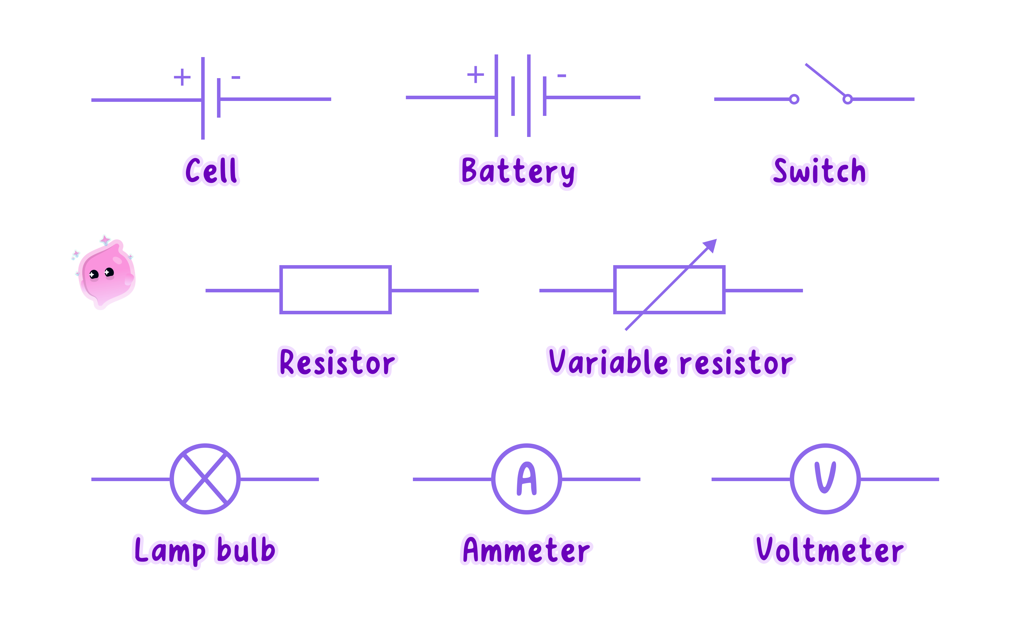
- A cell is drawn as two parallel lines of different lengths, where the long thin line is the positive terminal and the short thick line is the negative terminal.
- A battery is drawn as two or more cell symbols joined together, sometimes with a dashed line between the first and last cell.
- When the cells all face the same way, the potential difference of the battery is the sum of the potential differences of the cells, so two 1.5 V1.5\ \text{V}1.5 V cells give 3.0 V3.0\ \text{V}3.0 V.
- A d.c. power supply is usually drawn as two small open circles marked +++ and −-−, sometimes labelled with the potential difference it is set to.
- On a laboratory power supply, the positive terminal is normally red and the negative terminal is normally black.
- An open switch is drawn as a short line hinged at one end and lifted away from the contact, showing a gap that breaks the circuit.
- A closed switch is drawn with the line lying flat against the contact, showing that the circuit is complete.
Component symbols
Definition
Variable resistor
A resistor whose resistance can be adjusted to change the current in a circuit.
- A fixed resistor is drawn as a rectangle, and it has a set resistance that limits the current in a circuit.
- A variable resistor is drawn as a rectangle with a diagonal arrow through it, and moving its slider changes its resistance and so changes the current.
- A filament lamp is drawn as a circle with a cross inside it.
- A diode is drawn as a triangle pointing at a short bar, with the wire passing straight through both.
- The triangle points in the direction in which conventional current is allowed to flow through the diode.
- A light-dependent resistor (LDR) is drawn as a resistor rectangle, usually inside a circle, with two arrows pointing towards it to show light falling on it.
- An NTC thermistor is drawn as a resistor rectangle with a diagonal line through it that ends in a short horizontal tail.
- An ammeter is drawn as a circle containing the letter A, and a voltmeter is drawn as a circle containing the letter V.
- An ammeter is drawn in the line of the circuit, while a voltmeter is drawn on its own short loop that joins the circuit on either side of the component it measures.
Drawing and reading diagrams
- Draw circuit diagrams with a ruler and a sharp pencil, using only the standard symbols.
- Draw the wires so that each loop is closed, with no gaps except at an open switch.
- Mark every junction with a dot, and draw the cell or battery so that its long and short lines are clear.
- To read a diagram, start at the positive terminal and trace the path of conventional current around the circuit back to the negative terminal.
- Components that the current passes through one after another, with no junction between them, are in series.
- Components on separate branches between the same two junctions are in parallel.
- Check which way round any diode is drawn, because a diode pointing against the conventional current from the supply blocks the current in that part of the circuit.
Example
Reading a circuit diagram
- A circuit diagram shows two 1.5 V1.5\ \text{V}1.5 V cells facing the same way, a closed switch, a fixed resistor and a diode, all in one loop.
- The two cells form a battery with a potential difference of 1.5 V+1.5 V=3.0 V1.5\ \text{V} + 1.5\ \text{V} = 3.0\ \text{V}1.5 V+1.5 V=3.0 V.
- Conventional current leaves the long line of the battery and travels round the loop towards the short line.
- The triangle of the diode points in the same direction as this conventional current, so the diode lets the current pass and the circuit carries a current.
- If the battery is turned round, the conventional current tries to flow against the triangle of the diode, so there is no current in the loop.
Practical
Building a circuit from a circuit diagram
- Aim: to build a working circuit from a circuit diagram and check that every connection matches the diagram.
- Apparatus: a circuit diagram showing a d.c. power supply, a switch, a fixed resistor, a filament lamp, an ammeter and a voltmeter, the matching real components, a low-voltage d.c. power supply set to 6 V6\ \text{V}6 V and connecting leads with crocodile clips.
- Method, identifying the parts:
- Match each real component to its symbol on the diagram, and find the positive and negative terminals of the supply and of each meter.
- Lay the components out on the bench in roughly the same shape as the diagram, which makes the connections easier to follow.
- Method, wiring the circuit:
- With the supply switched off and the switch open, start at the positive terminal of the supply and connect the components of the main loop one after another, following the diagram.
- Fit the ammeter in the line of the loop, with its positive terminal on the side nearer the positive terminal of the supply.
- Add the voltmeter last, clipping its leads to either side of the component it is drawn across.
- Trace each lead with your finger and tick off the matching line on the diagram, so that every connection is checked once.
- Method, testing the circuit:
- Switch on the supply, close the switch briefly and check that the lamp lights and that both meters give a sensible positive reading.
- If nothing happens, open the switch and check each connection against the diagram again, looking for a loose clip or a gap in the loop.
- Results: a correctly built circuit lights the lamp, the ammeter shows a current and the voltmeter shows a potential difference smaller than the supply setting.
- Conclusion: following the diagram connection by connection produces a circuit that behaves as the diagram predicts.
- Watch out: a negative meter reading means the meter has been connected the wrong way round, and a voltmeter reading of zero with the lamp off usually means the loop is broken somewhere.
- Safety: keep the supply switched off while connecting leads, keep the potential difference low, and never join a lead straight across the two terminals of the supply.
Common Mistake
- Do not mix up the lines of the cell symbol, because the long line is positive and the short line is negative.
- Do not draw a lamp as an empty circle, because the cross inside the circle is what identifies a filament lamp.
- Do not forget the junction dots, because two lines crossing without a dot are not joined.
- Do not confuse conventional current with electron flow, because electrons move from negative to positive, in the opposite direction to the current shown on diagrams.
Exam technique
Drawing circuit diagrams
- When you draw a circuit, use a ruler, close every loop and check that each symbol matches the component named in the question.
- Draw the voltmeter on a separate loop across the component, because a voltmeter drawn in the line of the circuit is marked as wrong.
- When a question shows a diagram containing a diode, check which way the triangle points before deciding whether there is a current.
- When you are asked to identify a component, describe its symbol precisely, such as a rectangle with a diagonal arrow through it for a variable resistor.
Self review
- State which line of a cell symbol is the positive terminal.
- Describe the direction of conventional current around a circuit.
- Describe the circuit symbol for an NTC thermistor.
- State what a solid dot shows on a circuit diagram.
- Explain why a diode pointing against the conventional current stops the current in its part of the circuit.