Calculating in series circuits
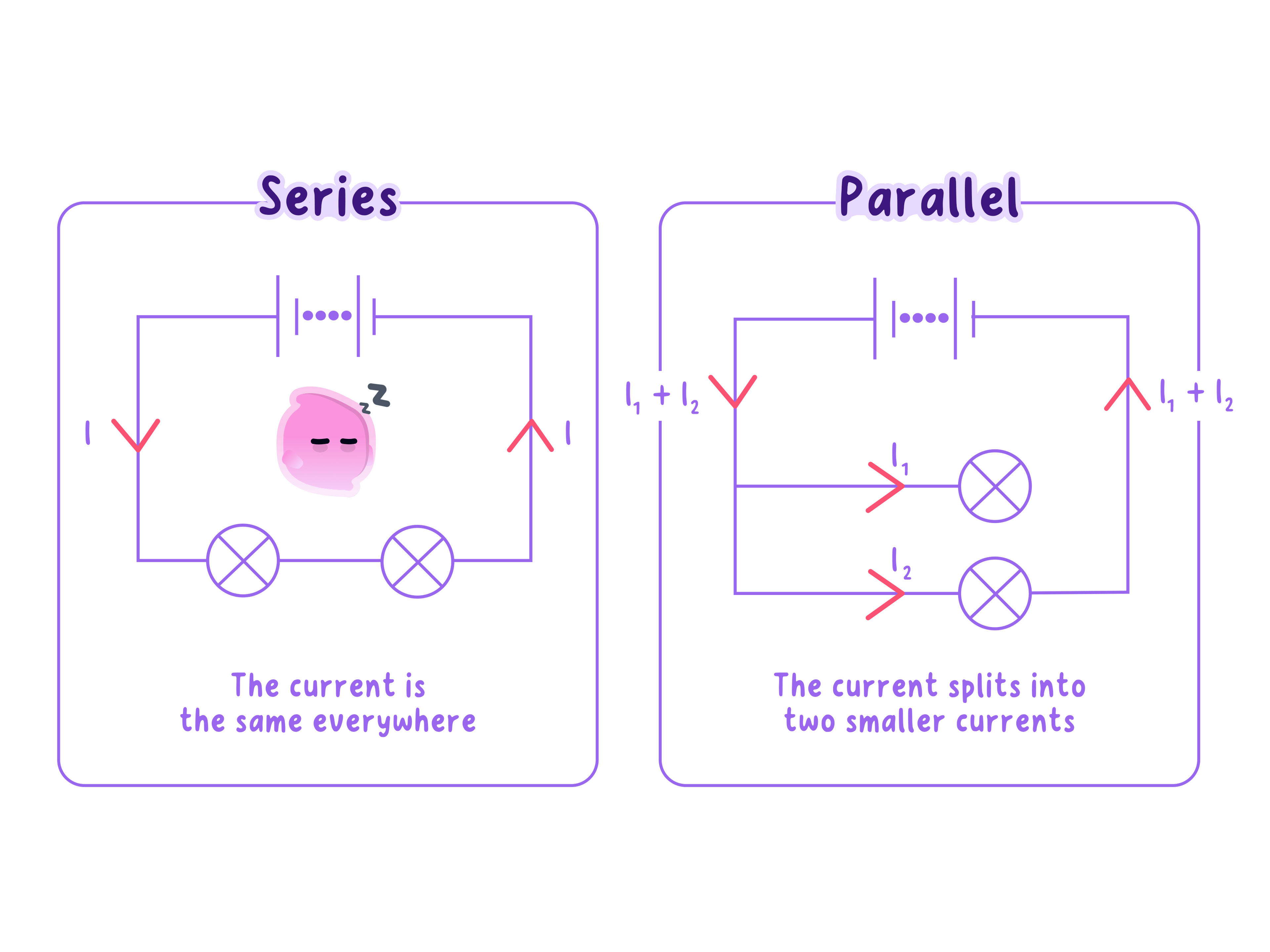
- In a series circuit, the current is the same through every component, so one current value is used for every component.
- The total resistance of components in series is the sum of their resistances, Rtotal=R1+R2R_{\text{total}} = R_1 + R_2Rtotal=R1+R2.
- The supply potential difference is shared, so the potential differences across the components add up to it, Vsupply=V1+V2V_{\text{supply}} = V_1 + V_2Vsupply=V1+V2.
- The equation V=IRV = IRV=IR can be applied to the whole circuit or to one component, as long as all three values belong to the same part.
- For the whole circuit, use the supply potential difference, the circuit current and the total resistance.
- For one component, use the potential difference across that component, the current through it and its own resistance.
- The component with the larger resistance has the larger potential difference across it, because the same current flows through both and V=IRV = IRV=IR.
Calculating in parallel circuits
- In a parallel circuit, the potential difference across each branch is the same as the supply potential difference.
- The current in each branch is found separately, using I=VRI = \dfrac{V}{R}I=RV with the supply potential difference and the resistance of that branch.
- The total current from the supply is the sum of the branch currents, Itotal=I1+I2I_{\text{total}} = I_1 + I_2Itotal=I1+I2.
- The total resistance of a parallel circuit is found by dividing the supply potential difference by the total current, Rtotal=VsupplyItotalR_{\text{total}} = \dfrac{V_{\text{supply}}}{I_{\text{total}}}Rtotal=ItotalVsupply.
- This total resistance is always smaller than the resistance of any single branch.
- The branch with the smaller resistance carries the larger current, because each branch has the same potential difference across it.
Solving circuit problems
- Decide first whether the components are in series, in parallel, or a mixture of both.
- Write down the values you know and label each one with the component it belongs to.
- Use the series and parallel rules to find any potential difference or current that is shared or added.
- Use V=IRV = IRV=IR for a single component or for the whole circuit to find the remaining unknown.
- Check the answer, for example by confirming that the series potential differences add up to the supply or that the branch currents add up to the total current.
Circuits with sensors
Definition
Photocell
A device that produces a potential difference, and so can drive a current, when light falls on it.
- The same rules apply when a circuit contains an NTC thermistor or an LDR, except that the resistance of the sensor depends on its surroundings.
- The resistance of a thermistor at a given temperature, or of an LDR at a given light intensity, is usually read from a graph and then used in the calculation.
- When a thermistor is in series with a fixed resistor, a rise in temperature lowers the thermistor resistance, so the circuit current increases and the potential difference across the thermistor falls.
- A photocell acts as a supply rather than a resistor, and the power it delivers is found by multiplying the potential difference across it by the current it drives, P=VIP = VIP=VI.
Example
Current and potential difference in a series circuit
- A 12 V12\ \text{V}12 V battery is connected in series with a 3.0 Ω3.0\ \Omega3.0 Ω resistor and a 5.0 Ω5.0\ \Omega5.0 Ω resistor.
- The two potential differences add up to 4.5 V+7.5 V=12 V4.5\ \text{V} + 7.5\ \text{V} = 12\ \text{V}4.5 V+7.5 V=12 V, which matches the battery.
Example
Currents in a parallel circuit
- A 6.0 V6.0\ \text{V}6.0 V supply is connected across a 12 Ω12\ \Omega12 Ω resistor and a 4.0 Ω4.0\ \Omega4.0 Ω resistor in parallel.
- Each branch has the full 6.0 V6.0\ \text{V}6.0 V across it.
- The total resistance of 3.0 Ω3.0\ \Omega3.0 Ω is smaller than the smaller branch resistance of 4.0 Ω4.0\ \Omega4.0 Ω, as expected for a parallel circuit.
Example
A thermistor in a series circuit
- An NTC thermistor is connected in series with a 1.0 kΩ1.0\ \text{k}\Omega1.0 kΩ resistor and a 6.0 V6.0\ \text{V}6.0 V supply, and at 20 ∘C20\ ^{\circ}\text{C}20 ∘C the thermistor has a resistance of 2.0 kΩ2.0\ \text{k}\Omega2.0 kΩ.
- At 60 ∘C60\ ^{\circ}\text{C}60 ∘C, the thermistor resistance falls to 500 Ω500\ \Omega500 Ω.
- Warming the thermistor has doubled the current and halved the potential difference across the thermistor.
Practical
Thermistor resistance and temperature
- Aim: to investigate how the resistance of an NTC thermistor changes as the temperature of the water around it is raised.
- Apparatus: an NTC thermistor sealed in a waterproof sleeve, a 250 cm3250\ \text{cm}^3250 cm3 beaker, a thermometer, a kettle, ice, a stirring rod, a 2 V2\ \text{V}2 V d.c. supply, a switch, a digital ammeter, a digital voltmeter and connecting leads.
- Method, setting up:
- Connect the supply, switch, ammeter and thermistor in series, with the voltmeter across the thermistor only.
- Half fill the beaker with a mixture of ice and cold water, and clamp the thermistor and the thermometer side by side in the water without touching the glass.
- Method, taking readings:
- Stir the water, wait until the thermometer reading is steady, then close the switch and record the temperature, current and potential difference.
- Open the switch, add a little hot water from the kettle to raise the temperature by about 10 ∘C10\ ^{\circ}\text{C}10 ∘C, stir, and wait for the readings to settle again.
- Continue in steps of about 10 ∘C10\ ^{\circ}\text{C}10 ∘C up to about 80 ∘C80\ ^{\circ}\text{C}80 ∘C, then repeat the whole run and calculate the mean resistance at each temperature using R=VIR = \dfrac{V}{I}R=IV.
- Plot resistance on the vertical axis against temperature on the horizontal axis and draw a smooth curve of best fit.
- Results: the resistance falls steeply at first and then more gradually, for example from several thousand ohms near 0 ∘C0\ ^{\circ}\text{C}0 ∘C to a few hundred ohms near 80 ∘C80\ ^{\circ}\text{C}80 ∘C.
- Conclusion: the resistance of an NTC thermistor decreases as its temperature increases, and the change is largest at low temperatures.
- Watch out: the thermistor takes time to reach the temperature of the water, and a large current would warm it above the water temperature, so keep the supply potential difference low and close the switch only for each reading.
- Safety: take care when pouring water from the kettle, keep the electrical connections dry and above the water, and use only a low-voltage supply.
Practical
LDR resistance and light intensity
- Aim: to investigate how the resistance of an LDR changes with the intensity of the light falling on it.
- Apparatus: an LDR, a bench lamp, a metre rule, a light meter if available, a 2 V2\ \text{V}2 V d.c. supply, a switch, a digital ammeter, a digital voltmeter and connecting leads, used in a darkened room.
- Method:
- Connect the supply, switch, ammeter and LDR in series, with the voltmeter across the LDR only.
- Clamp the LDR facing the lamp at the zero end of the metre rule, so the lamp shines straight onto it.
- Place the lamp 10 cm10\ \text{cm}10 cm from the LDR, record the current and potential difference, and calculate the resistance using R=VIR = \dfrac{V}{I}R=IV.
- Move the lamp back in steps of 10 cm10\ \text{cm}10 cm up to 60 cm60\ \text{cm}60 cm, taking readings at each distance, or record the light intensity with the light meter placed where the LDR sits.
- Repeat the whole set and calculate the mean resistance at each distance.
- Variables: the independent variable is the distance of the lamp, which sets the light intensity, the dependent variable is the resistance of the LDR, and the control variables are the lamp, the angle of the LDR and the background light.
- Results: the resistance of the LDR increases as the lamp is moved further away.
- Conclusion: the resistance of an LDR decreases as the light intensity falling on it increases.
- Watch out: stray light from windows or other groups changes the readings, so work in a darkened room and keep the LDR pointing straight at the lamp.
- Safety: the bench lamp becomes hot, so move it by its base and keep leads away from the bulb.
Practical
Photocell power, area and distance
- Aim: to investigate how the power output of a photocell depends on its illuminated area and on its distance from a light source.
- Apparatus: a small photocell (solar cell), a bench lamp, a metre rule, opaque card, a 100 Ω100\ \Omega100 Ω resistor, a digital ammeter, a digital voltmeter and connecting leads, used in a darkened room.
- Method, changing the area:
- Connect the photocell, ammeter and resistor in series, with the voltmeter across the photocell.
- Place the lamp 20 cm20\ \text{cm}20 cm from the photocell and record the current and potential difference with the whole cell uncovered.
- Cover one quarter, then one half, then three quarters of the cell with opaque card, recording the readings each time.
- Method, changing the distance:
- Uncover the whole cell and move the lamp to 10 cm10\ \text{cm}10 cm, 20 cm20\ \text{cm}20 cm, 30 cm30\ \text{cm}30 cm, 40 cm40\ \text{cm}40 cm and 50 cm50\ \text{cm}50 cm, recording the readings at each distance.
- For every reading, calculate the power output using P=VIP = VIP=VI, and repeat each run to find a mean.
- Results: the power output rises as more of the cell is uncovered, and it falls as the lamp is moved further away.
- Conclusion: a photocell delivers more power when a larger area is illuminated and when it is closer to the light source, because more light energy reaches it every second.
- Watch out: keep the distance fixed while changing the area and keep the area fixed while changing the distance, and keep the cell facing the lamp at the same angle throughout.
- Safety: the lamp becomes hot, so do not touch the bulb, and switch it off between runs.
Common Mistake
- Do not mix values from different parts of a circuit in V=IRV = IRV=IR, such as the supply potential difference with the resistance of only one component.
- Do not add the resistances of parallel branches together, because that gives the total resistance of a series circuit.
- Do not forget that every branch of a parallel circuit has the full supply potential difference across it.
Exam technique
Circuit calculations
- Write each step on its own line with the equation, the substitution and the answer with its unit, so that the method marks can be awarded even if a later value is wrong.
- Label each value with its component, such as V1V_1V1 or ItotalI_{\text{total}}Itotal, so that the examiner can follow which part of the circuit you are working on.
- Finish by checking that the potential differences or currents add up correctly, because this catches most mistakes.
Self review
- State the rule for the potential differences across components in series.
- Calculate the total resistance of a 6.0 Ω6.0\ \Omega6.0 Ω resistor and a 9.0 Ω9.0\ \Omega9.0 Ω resistor in series.
- Calculate the current in a 3.0 Ω3.0\ \Omega3.0 Ω branch connected in parallel across a 6.0 V6.0\ \text{V}6.0 V supply.
- Explain why the total resistance of a parallel circuit is smaller than the resistance of any branch.
- Describe how the potential difference across a thermistor in a series circuit changes as it warms up.