12.1.1 Magnetic poles
Magnets and magnetic poles
Magnet
A magnet is an object that produces a magnetic field around itself and exerts non-contact forces on other magnets and on magnetic materials.
Magnetic pole
A magnetic pole is one of the two regions of a magnet, called north and south, where the magnetic field is most concentrated and the magnetic force is strongest.
Non-contact force
A non-contact force is a force that one object exerts on another without the two objects touching.
- A magnet produces a magnetic field in the space around it, and any other magnet placed in that space feels a push or a pull.
- Every magnet has exactly two poles, and they always come as a pair: one north-seeking pole, labelled N, and one south-seeking pole, labelled S.
- The full names come from what a freely suspended magnet does. Left to hang on a thread, it turns until one particular end points towards the Earth's geographic north, and that end is the north-seeking pole.
- In diagrams and written answers the shortened names north pole and south pole are used, and both spellings of the idea earn credit.
- The poles are the two regions where the magnetic field is most concentrated, so the magnetic force produced by a bar magnet is strongest at its ends and weakest around its middle.
- A bar magnet is usually drawn with the north pole shaded blue and the south pole shaded red, and the letters N and S printed on the correct ends.
- The forces between magnets are non-contact forces. Two magnets do not need to touch, and the push or pull acts straight across the air gap between them.
- Because magnetic force is a non-contact force, it still acts through thin non-magnetic barriers such as paper, a plastic ruler or a glass sheet.
- A single pole on its own does not exist. Snapping a bar magnet in half gives two shorter bar magnets, each with a full north pole and a full south pole at its ends.
- Magnetism is a property of the object, not something stored up and used. A magnet keeps exerting forces indefinitely without running down like a battery.
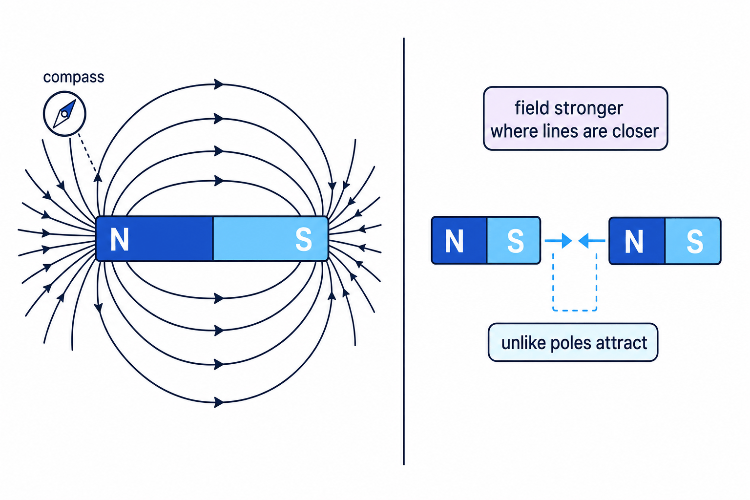
Magnetic poles always exist in pairs, and the magnetic force between them acts across a gap without the magnets touching.
Attraction and repulsion
- Whether two magnets pull together or push apart is decided by which pair of poles is facing across the gap.
- Unlike poles attract. A north pole facing a south pole gives a pull, so each magnet is pushed towards the other.
- Like poles repel. A north pole facing a north pole gives a push apart, and so does a south pole facing a south pole.
- There are only four possible pairings, and the rule sorts all of them:
- north facing south gives attraction
- south facing north gives attraction
- north facing north gives repulsion
- south facing south gives repulsion
- The two magnets always experience forces of the same size acting in opposite directions, so when they attract, each one is pulled towards the other rather than one magnet doing all the work.
- Turning one magnet through 180∘180^\circ180∘ swaps which of its poles faces the other magnet, so attraction becomes repulsion and repulsion becomes attraction without moving the second magnet at all.
- The size of the magnetic force grows sharply as the gap between the poles is reduced, and falls away quickly as the magnets are separated. Doubling the separation reduces the force by much more than half.
- Repulsion is the only certain test that an object is a magnet. Attraction alone is not enough, because a magnet also attracts an unmagnetised piece of iron or steel.
- Two identical bar magnets pushed north pole to north pole will spring apart if one is released, because the repulsive force acts along the line joining the poles.
Predicting attraction or repulsion
- Two bar magnets lie end to end on a bench with a 2 cm2\ \text{cm}2 cm gap. The left magnet has its south pole facing the gap and the right magnet has its north pole facing the gap.
- Identify the pair of poles facing each other across the gap: a south pole and a north pole.
- These are unlike poles, because one is north and one is south.
- Unlike poles attract, so each magnet experiences a force pulling it towards the other and the gap closes.
- If the right magnet is now turned end for end, a south pole faces the gap instead. The poles are then alike, so the magnets repel and the gap widens.
Investigating the force between two magnets
- Aim: to compare the forces produced by like and unlike poles and to find how the force between two magnets changes with the separation of the poles.
- Apparatus: two identical bar magnets, a digital top-pan balance reading to 0.01 g0.01\ \text{g}0.01 g, a non-magnetic clamp stand and boss, a wooden or plastic block, a set square, a millimetre ruler or vernier callipers, and adhesive putty.
- Variables: the separation of the two poles is the independent variable, the reading change on the balance is the dependent variable, and the pair of magnets, the pole combination, the alignment of the magnets and the balance zero are all kept the same.
- Method, setting up:
- Stand the balance on a level bench well away from iron or steel objects, since a nearby radiator or table leg can attract the magnets sideways and spoil the reading.
- Fix one bar magnet flat on the balance pan with a small piece of adhesive putty so that one pole points vertically upwards, then press the tare or zero button so the balance reads 0.00 g0.00\ \text{g}0.00 g.
- Clamp the second bar magnet in the non-magnetic clamp directly above the first, with its lower pole pointing straight down at the pole below it and the two magnets in line.
- Check the alignment with a set square, because a tilted upper magnet gives a sideways force component that the balance cannot detect.
- Method, taking readings:
- Set the vertical gap between the two facing poles to 10 mm10\ \text{mm}10 mm, measured with the ruler or callipers held against the sides of the magnets.
- Read the balance and record whether the reading is positive or negative. A negative reading means the upper magnet is pulling the lower magnet upwards, so the poles are attracting. A positive reading means the upper magnet is pushing down, so the poles are repelling.
- Raise the clamp, lower it again to the same gap and take a second and third reading, then calculate a mean so that a single misplaced measurement does not decide the result.
- Repeat for gaps of 20 mm20\ \text{mm}20 mm, 30 mm30\ \text{mm}30 mm, 40 mm40\ \text{mm}40 mm and 50 mm50\ \text{mm}50 mm, re-zeroing the balance between sets.
- Turn the upper magnet over so the opposite pole now faces down, and repeat the whole set of gaps. The pole combination has changed from like to unlike, or from unlike to like.
- Processing: convert each mean balance reading in grams to a force in newtons using F=mgF=mgF=mg with g=10 N/kgg=10\ \text{N/kg}g=10 N/kg, remembering to convert grams to kilograms first, so a reading of 4.0 g4.0\ \text{g}4.0 g corresponds to F=0.0040×10=0.040 NF=0.0040\times10=0.040\ \text{N}F=0.0040×10=0.040 N.
- Expected pattern: like poles give a downward push and unlike poles give an upward pull, and for both combinations the size of the force rises steeply as the gap is reduced, so a graph of force against separation is a curve that falls away rather than a straight line.
- Watch out: stray iron near the bench, a tilted upper magnet, forgetting to re-zero the balance, reading the gap between the magnet edges rather than the pole faces, and pressing the clamp so far down that the two magnets snap together and damage the pan.
- Safety: keep the strong magnets away from phones, bank cards and laptops, warn anyone with a heart pacemaker to stay clear, and support the clamp stand so it cannot topple onto fingers.
Answering questions on poles
- For a state or give command word, one word is enough: write attract or repel.
- For an explain command word, name the pair of poles first and then quote the rule, for example that the magnets repel because two north poles are like poles and like poles repel.
- Use the technical words magnetic poles, attract and repel rather than everyday phrases such as stick together or push away, which examiners often refuse to credit.
- If a diagram shows unlabelled magnets, mark the poles on the diagram yourself before writing anything, so that the pairing across the gap is obvious.
- When asked how to prove that an object is a magnet, the mark is for repulsion, so describe bringing a known pole up to it and looking for a push.
- Do not write that north poles attract. A north pole attracts a south pole and repels another north pole.
- Do not say that the magnets touch to produce the force. Magnetic force is a non-contact force that acts across a gap.
- Do not use attraction on its own to prove that something is a magnet, because an unmagnetised iron nail is also attracted.
- Do not claim that cutting a magnet in half separates a north pole from a south pole. Each half is a complete magnet with two poles.
- Name the two poles of a magnet and state which end of a freely suspended magnet points towards geographic north.
- State what happens when a north pole is brought close to a south pole, and when a south pole is brought close to a south pole.
- Explain why the force between two magnets is described as a non-contact force.
- Describe how the force between two magnets changes as the gap between their poles is made smaller.
- Explain why repulsion, and not attraction, is the reliable test for whether an object is a magnet.
12.1.2 Magnetic materials; permanent and induced magnets
Magnetic materials
Magnetic material
A magnetic material is a material that is attracted by a magnet and that can itself be magnetised, such as iron, steel, nickel and cobalt.
- Only a small number of materials are magnetic. The four you are expected to name are iron, steel, nickel and cobalt.
- Steel is an alloy of iron with a small amount of carbon, so it behaves magnetically because of the iron it contains.
- Being a metal is not the same as being magnetic. Copper, aluminium, brass, gold and silver are all metals, yet a magnet does not attract any of them.
- Non-metals such as wood, plastic, glass, rubber and card are never magnetic.
- This difference is put to work in recycling. A rotating magnetic drum lifts steel food tins out of a moving stream of waste while aluminium drinks cans travel past untouched.
- A magnetic material can do two separate things: it is attracted by a magnet, and it can itself be magnetised so that it becomes a magnet.
- A piece of magnetic material can be magnetised by stroking it repeatedly in one direction with one pole of a permanent magnet, or by placing it inside a coil carrying a current.
- A magnet can be demagnetised by heating it strongly, by hammering it, or by placing it inside a coil carrying an alternating current that is then slowly withdrawn.
Permanent and induced magnets
Permanent magnet
A permanent magnet is a magnet that produces its own magnetic field all of the time and keeps that field when it is taken away from any other magnetic field.
Induced magnet
An induced magnet is a magnetic material that becomes a magnet only while it is placed inside another magnetic field.
- A permanent magnet needs nothing done to it. It has its own north pole and south pole, it produces a magnetic field at all times, and that field is still there when every other magnet is taken away.
- An induced magnet borrows its magnetism. A piece of magnetic material becomes a magnet only while it sits inside the field of another magnet, and it loses most or all of that magnetism when it is taken out of the field.
- The chain of reasoning for induced magnetism runs in four steps:
- The magnetic material is placed inside the magnetic field of a permanent magnet.
- The field magnetises the material, so the material becomes an induced magnet with its own poles.
- The end of the material nearest the permanent magnet always becomes the opposite pole to the pole it is facing.
- Unlike poles attract, so the material is pulled towards the permanent magnet.
- Because the nearest end always takes the opposite pole, induction always produces attraction. A permanent magnet cannot repel an unmagnetised piece of iron whichever pole is offered to it.
- This is why a chain of paper clips can hang from a single magnet. The first clip becomes an induced magnet, its far end becomes a free pole, and that pole induces magnetism in the next clip down the chain.
- Take the permanent magnet away and the chain falls apart, because each clip loses the induced magnetism that was holding the next one on.
- How much magnetism is kept afterwards depends on the material. Iron keeps almost none, while steel can keep a great deal and may end up as a weak permanent magnet.
Working out the induced poles on a nail
- The north pole of a permanent bar magnet is brought close to the head of an unmagnetised iron nail, with the point of the nail furthest away.
- The nail is iron, which is a magnetic material, so the magnet's field magnetises it and the nail becomes an induced magnet.
- The nearest end takes the opposite pole, so the head of the nail becomes an induced south pole and the point becomes an induced north pole.
- A north pole now faces an induced south pole across the gap. These are unlike poles, so the nail is attracted and moves towards the magnet.
- If the bar magnet is turned round so that its south pole faces the head, the induced poles swap over and the head becomes an induced north pole. The nail is still attracted.
Choosing the right magnetic material
Temporary magnetic material
A temporary magnetic material is a magnetic material that is easily magnetised but loses almost all of its magnetism as soon as the magnetising field is removed.
- Magnetic materials are sorted by how well they hold on to magnetism once the magnetising field has gone.
- Permanent magnetic materials are harder to magnetise in the first place but keep their magnetism well. Steel is the standard school example, and alloys containing nickel and cobalt make the strongest permanent magnets used in industry.
- Temporary magnetic materials magnetise very easily but lose that magnetism just as easily. Iron is the standard example.
- Use a permanent magnetic material whenever the object has to stay magnetic without any power supply:
- compass needles, which must go on pointing along the Earth's field for years
- fridge magnets and the catches that hold cupboard doors shut
- the fixed magnets inside loudspeakers, headphones and electric motors
- magnetic tool holders and screwdriver tips that keep hold of steel screws
- Use a temporary magnetic material whenever the magnetism has to be switched on and off:
- the iron core of a scrapyard crane magnet, so a car body can be lifted and then dropped
- the iron core inside an electric bell, which must release the hammer between strikes
- the iron core in a relay, so a small current can open and close a separate switch
- magnetic door locks that release the moment the current is cut, which is what makes them safe in a fire
- Putting a steel core in a crane magnet would be a design fault. The steel would stay magnetised after the current was switched off, so the load would not drop.
Testing materials for magnetism and induced magnetism
- Aim: to sort a set of materials into magnetic and non-magnetic, and to compare how much magnetism an iron nail and a steel nail keep after they are removed from a magnetic field.
- Apparatus: a strong bar magnet, an iron nail, a steel nail, samples of copper, aluminium, brass, wood and plastic, a box of small steel paper clips, a plotting compass, a wooden ruler and a wooden or plastic tray.
- Variables: the material under test is the independent variable, the number of paper clips picked up is the dependent variable, and the magnet used, the pole used, the contact time and the size of the paper clips are all kept the same.
- Method, sorting the materials:
- Lay the samples out on a wooden tray so that they are not touching each other.
- Bring the north pole of the bar magnet slowly up to each sample and record whether it is attracted, then repeat with the south pole.
- A magnetic material is attracted by both poles. Nothing in the set should be repelled, because none of the samples starts out as a magnet.
- Record the results in a table with columns for the material, the result with the north pole, the result with the south pole and the conclusion.
- Method, comparing iron and steel:
- Check first that both nails start unmagnetised by holding each one near the plotting compass. An unmagnetised nail attracts the needle whichever end is used, so it must not push the needle away.
- Hold the iron nail against one pole of the bar magnet and lower its free end into the pile of paper clips. Count how many clips hang from it while it is still touching the magnet.
- Pull the nail away from the bar magnet without shaking it, and count how many clips are still hanging from it. This second count measures the magnetism the nail has kept.
- Stroke the nail thirty times in the same direction with one pole of the magnet, lifting the magnet clear at the end of every stroke, then repeat the paper-clip count.
- Repeat the whole sequence with the steel nail, using the same pole, the same number of strokes and the same pile of clips.
- Carry out three trials for each nail and calculate a mean number of clips, since the clips tangle and a single count is unreliable.
- Expected pattern: iron, steel, nickel and cobalt are attracted while copper, aluminium, brass, wood and plastic are not. Both nails hold clips while touching the magnet, but the iron nail drops almost all of them once the magnet is removed, whereas the steel nail keeps a noticeable number and can be shown with the compass to have become a weak permanent magnet.
- Watch out: nails that were already magnetised from an earlier lesson, stroking back and forth instead of in one direction, dragging the magnet back across the nail on the return stroke, using clips of different sizes between trials, and holding the nail so close to the pile that clips are picked up by the bar magnet itself.
- Safety: nail points are sharp, so handle them by the head, keep the magnets well away from phones and bank cards, and collect spilt paper clips off the floor straight away.
Naming a material and its property
- Questions that ask you to choose a material carry two marks: one for the material and one for the property. Naming steel without saying that it keeps its magnetism scores half.
- Write the property as a full reason, for example that iron suits an electromagnet because it is easily magnetised and easily demagnetised.
- For an explanation of attraction by induction, give the three linked stages in order: the material becomes an induced magnet, the nearest end becomes the opposite pole, and unlike poles attract.
- The mark most often dropped is the middle one. Say which pole is induced at which end rather than writing only that the nail becomes magnetic.
- If a question asks whether an object is a permanent magnet or an induced magnet, look for what happens after the other magnet is removed. Magnetism that disappears means induced.
- Do not write that all metals are magnetic. Only iron, steel, nickel and cobalt are magnetic among the metals you meet.
- Do not say that an induced magnet can be repelled by a permanent magnet. The nearest end always takes the opposite pole, so induction gives attraction every time.
- Do not confuse a magnetic material with a magnet. An iron nail is a magnetic material at all times, but it is only a magnet while it is magnetised.
- Do not mix up the two properties of steel and iron. Steel is the harder one to magnetise and the better one at keeping magnetism.
- Name four magnetic materials and two metals that are not magnetic.
- State the difference between a permanent magnet and an induced magnet.
- Explain why an unmagnetised steel paper clip is attracted to either pole of a bar magnet.
- Give the material used for the core of a scrapyard crane magnet and the property that makes it suitable.
- Describe how you would show experimentally that steel keeps more magnetism than iron.
12.1.3 Magnetic fields
Magnetic fields and field lines
Magnetic field
A magnetic field is the region around a magnet or a current-carrying conductor in which a magnetic material or another magnet experiences a force.
Magnetic field line
A magnetic field line is a line drawn to represent a magnetic field, whose arrow gives the direction of the force on the north pole of a small test magnet placed at that point.
- A magnetic field fills the space around a magnet. It cannot be seen, so it is drawn using magnetic field lines, which are a model rather than real threads in the air.
- A field-line diagram carries three separate pieces of information at once:
- the shape of the field, given by the paths the lines follow
- the direction of the field, given by the arrowheads drawn on the lines
- the relative strength of the field, given by how closely the lines are packed together
- The arrow on a field line points the way a free north pole would be pushed if it were placed at that point.
- Field strength is read from the spacing of the lines and nothing else. Closely packed lines mean a strong field, widely spaced lines mean a weak field.
- Two field lines never cross. If they did, the field at the crossing point would have two directions at once, which is impossible.
- The number of lines drawn is a choice made by whoever draws the diagram. Only the way the spacing changes from place to place carries any meaning.
The closer together the magnetic field lines are drawn, the stronger the magnetic field is at that point.
The field around a bar magnet
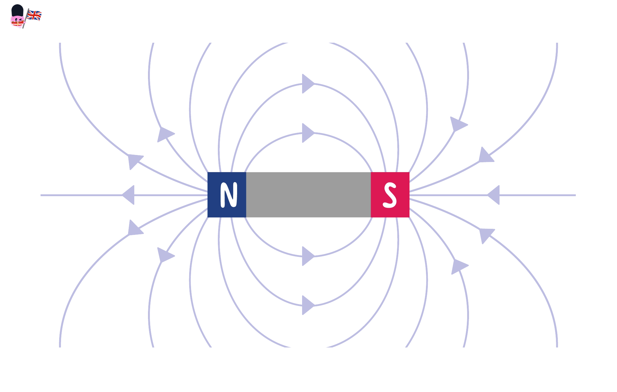
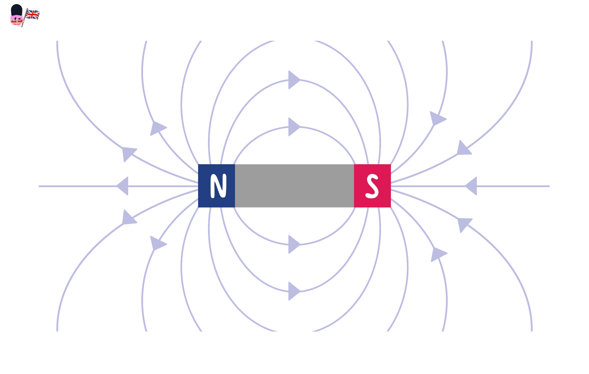
- Outside a bar magnet the field lines are curved and they always run from the north pole to the south pole.
- The lines leave the magnet at the north pole, sweep round through the space beside the magnet, and return to it at the south pole, forming closed loops.
- The pattern is symmetrical about the long axis of the magnet, so the loops on one side mirror the loops on the other.
- The lines are packed most tightly at the two poles, which is why the field is strongest there and why a bar magnet picks up the most paper clips at its ends.
- Moving away from the magnet the lines spread apart, so the field gets weaker with distance. At the midpoint of the long side the field is at its weakest.
- When you are asked to draw the field around a bar magnet, four things earn the marks: curved lines, arrows pointing from north to south, lines closest together at the poles, and no lines crossing.
- A horseshoe magnet is a bar magnet bent round so that its two poles face each other, which crowds the field lines into the narrow gap and gives a strong field in a small space.
Fields between two magnets
Uniform magnetic field
A uniform magnetic field is a magnetic field that has the same strength and the same direction at every point within a region.
Neutral point
A neutral point is a position where two overlapping magnetic fields are equal in size and opposite in direction, so the overall field there is zero.
- When two magnets are placed near each other, their fields combine into a single pattern, and the shape of that pattern depends on which poles face each other.
- Unlike poles facing: the field lines run straight across the gap from the north pole of one magnet into the south pole of the other, and the two magnets are pulled together.
- Like poles facing: the field lines curve sharply away from each other and bulge outwards, because the two fields push in opposite directions in the gap.
- Directly between two equal like poles there is a neutral point. The two fields cancel exactly, so no field lines pass through it and a plotting compass placed there would not settle in any particular direction.
- The narrow region between two unlike poles held a short distance apart is close to a uniform magnetic field, which is why this arrangement is used whenever a steady, even field is needed.
- A uniform field is drawn with lines that are:
- straight rather than curved
- parallel to one another, because the direction is the same everywhere
- equally spaced, because the strength is the same everywhere
- all arrowed in the same direction, from the north pole towards the south pole
- The field near the open ends of the gap bends outwards and stops being uniform, so the uniform region is only the central part between the pole faces.
- Every field that is not uniform is called non-uniform. The field around a single bar magnet is non-uniform, because both the direction and the spacing change from point to point.
Comparing field strength at two points
- A field diagram of a bar magnet is marked with point X just beyond the north pole and point Y level with the middle of the magnet and the same distance from its surface.
- Look only at the spacing of the lines, not at their length or their curvature.
- At X the lines are crowded close together, because every line leaving the magnet is funnelled through the pole.
- At Y the same lines have spread out sideways, so the gaps between them are wider.
- The field is therefore stronger at X, because the field lines there are more closely spaced.
Revealing the field shape with iron filings
- Aim: to make the shape of the magnetic field around a bar magnet visible, and to compare the patterns produced when two magnets are arranged to attract and to repel.
- Apparatus: two bar magnets, a stiff sheet of white card or a clear acrylic sheet, a pepper-pot shaker of fine iron filings, a sheet of clingfilm or a thin polythene bag, a wooden ruler and a camera or phone.
- Variables: the arrangement of the magnets is the independent variable, the pattern taken up by the filings is the dependent variable, and the magnets used, the amount of filings, the height of the card and the tapping are all kept the same.
- Method, one magnet:
- Wrap the bar magnet loosely in clingfilm so that filings can be shaken off cleanly at the end, then lay it flat on the bench.
- Rest the card centrally over the magnet so it lies flat and does not rock, and lightly pencil round the magnet on the card so its position is recorded.
- Sprinkle the iron filings thinly and evenly over the whole card from a height of about 20 cm20\ \text{cm}20 cm. A thick pile clumps together and hides the pattern.
- Tap the edge of the card gently and repeatedly with the ruler. Each tap lifts the filings just clear of the surface so that friction stops holding them and they can swing into line with the field.
- Photograph the pattern from directly above, then sketch it onto the card outline.
- Method, two magnets:
- Clear the filings back into the shaker, then set the two magnets end to end with a gap of about 3 cm3\ \text{cm}3 cm and a north pole facing a south pole.
- Weight or tape the magnets down so they cannot snap together, replace the card, sprinkle and tap as before, and record the pattern.
- Turn one magnet round so that two like poles now face across the same gap, and repeat the whole procedure.
- Expected pattern: one magnet gives curved loops that are densest at the poles. Unlike poles give lines running straight across the gap and a dense, nearly even region between the pole faces. Like poles give lines that bend away from the gap and a bare patch at the neutral point where almost no filings settle.
- Limitation: iron filings show the shape of the field but they carry no arrowheads, so the pattern alone cannot tell you which way round the field points.
- Watch out: too many filings, tapping too hard so the pattern scatters, a card that is bowed or lifted off the magnet, and stray filings left on the bench from a previous group.
- Safety: keep iron filings well away from eyes and never blow them off a surface, wash your hands afterwards, and use the clingfilm so the filings do not become stuck fast to the magnets.
Describing a field diagram
- A describe question about a field pattern is usually marked on three things: the shape of the lines, the direction of the arrows, and what the spacing tells you about strength.
- Say from north to south and add the words outside the magnet, since that is where the rule applies.
- The mark students most often lose is the strength one. Write that the lines are closest together at the poles, so the field is strongest there.
- In a drawing question, put an arrowhead on every line before you hand it in. Unarrowed lines show shape only and cannot score the direction mark.
- For a uniform field, the three words that earn credit are straight, parallel and equally spaced.
- Do not draw or describe the field outside a magnet as running from south to north. Outside the magnet the direction is north to south.
- Do not judge field strength from how long or how thick a line is drawn. Strength is shown only by how close the lines are to each other.
- Do not let field lines cross or stop in mid-air. Every line outside the magnet begins at a north pole and ends at a south pole.
- Do not call the field around a single bar magnet uniform. Its lines are curved and unevenly spaced, so it is non-uniform.
- State the three pieces of information a magnetic field line diagram gives you.
- Describe the shape and direction of the field lines outside a bar magnet.
- Explain how a field diagram shows where the field is strongest.
- Give the three features of the field lines drawn for a uniform magnetic field, and explain what each one represents.
- Explain what a neutral point is and where one is found between two magnets.
- State why iron filings on their own cannot show the direction of a magnetic field.
12.1.4 Plotting compasses and the Earth's magnetic field
Plotting compasses
Plotting compass
A plotting compass is a small magnetised needle on a pivot that is free to turn and comes to rest along the magnetic field line at its position.
- A plotting compass is simply a very small bar magnet mounted on a low-friction pivot inside a clear case, so it is free to swing round in the horizontal plane.
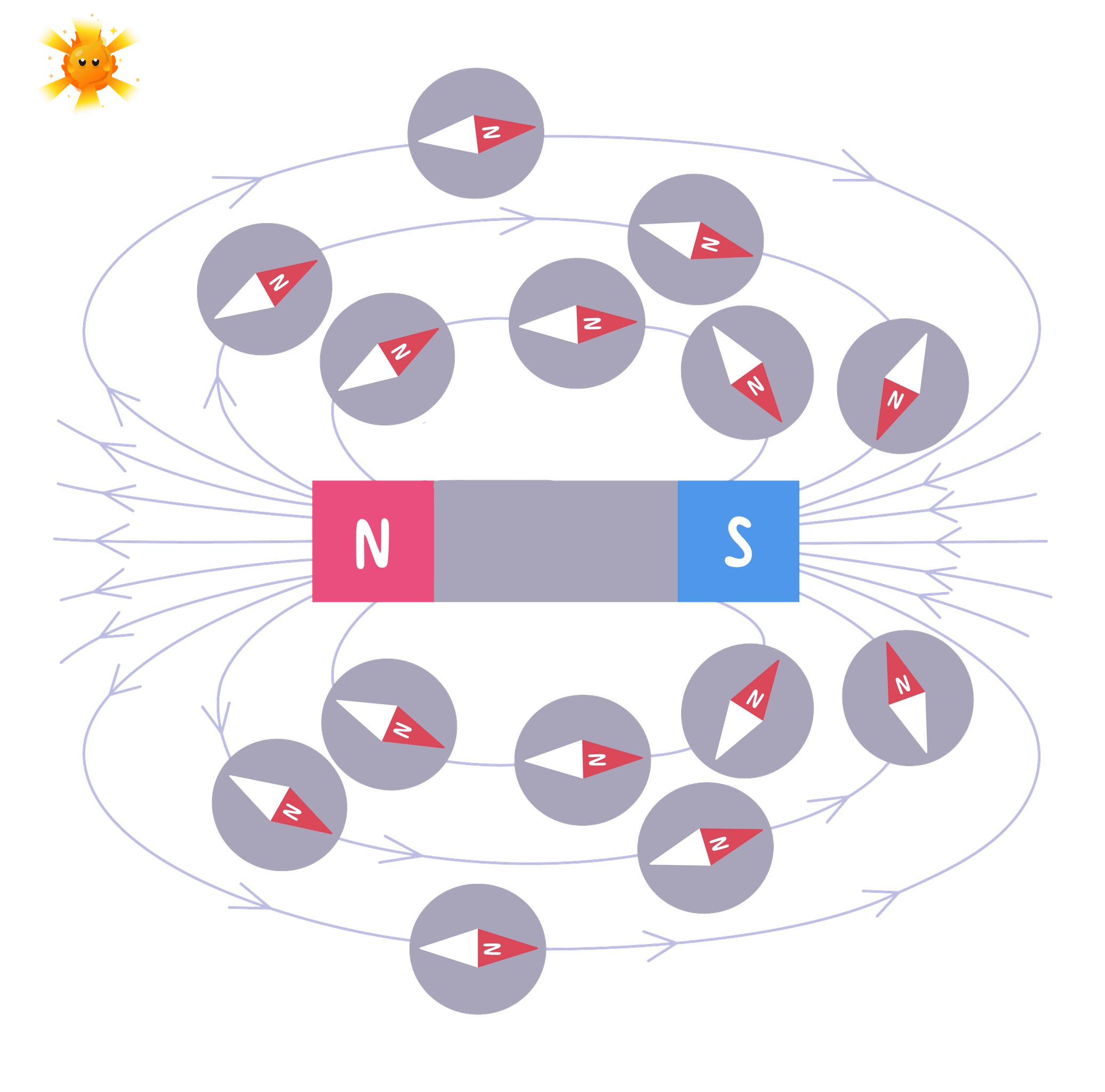
- Placed in a magnetic field, the needle turns until it lies along the field line passing through that point, and then it stops.
- It turns because the field pulls the needle's north pole one way and its south pole the opposite way. These two forces act at opposite ends of the needle, so they twist it rather than dragging it sideways.
- Once the needle is lined up with the field the two forces are directly opposed, the twist disappears, and the needle settles.
- The north-seeking end of the needle, usually the coloured or arrow-shaped end, points the way the field is directed at that point.
- Near a bar magnet the compass therefore points away from the magnet's north pole and towards its south pole, matching the arrows drawn on a field-line diagram.
- A compass measures direction only. It gives no reading for how strong the field is, so the shape of a whole field has to be built up by moving the compass from point to point.
- Ring several compasses round a magnet at once and each needle points a slightly different way, because each one is responding to the field at its own position.
- This is the advantage the compass has over iron filings. The filings line up with the field but give no arrows, while the compass needle carries its own arrowhead.
Mapping a magnetic field with a plotting compass
- Aim: to plot the shape and the direction of the magnetic field around a bar magnet, and to locate the field's direction at chosen points.
- Apparatus: a bar magnet, a plotting compass, a large sheet of plain A3 paper, a sharp pencil, a wooden ruler, a drawing board or wooden bench, and a soft pencil for shading in the finished lines.
- Variables: the starting position of the compass is the independent variable, the direction taken up by the needle is the dependent variable, and the magnet, its position on the paper and the absence of other magnets nearby are all kept the same.
- Method, setting up:
- Work on a wooden bench well away from radiators, steel table frames, other magnets and mains cables, all of which pull the needle off the true direction.
- Lay the paper flat, place the bar magnet near the middle and draw round it in pencil so that its outline and its pole positions are recorded permanently.
- Label the outline with N and S, and do not move the magnet again until the whole map is finished.
- Method, tracing one field line:
- Put the compass on the paper with its tail end just touching the north pole of the magnet, and wait for the needle to come fully to rest.
- Mark a pencil dot on the paper at the tip of the north-seeking end of the needle, and a second dot at the tail.
- Slide the compass forward until its tail sits exactly on the dot you made at the tip, then let the needle settle again and mark a new dot at the new tip.
- Keep leapfrogging the compass in this way, one needle length at a time, until the trail of dots arrives back at the south pole of the magnet.
- Join the dots with a single smooth curve rather than a set of straight dashes, and add arrowheads pointing from the north pole towards the south pole.
- Method, completing the map:
- Start again from a different point on the north pole and trace a second line, then a third, until at least six or eight lines cover both sides of the magnet.
- Include lines that start at the corners and along the sides of the magnet, not only from the very ends, so that the full loop shape appears.
- As a check, place the compass at three or four random points on the finished map and confirm that the needle lies along the line already drawn there.
- Expected pattern: the completed sheet shows curved closed loops running from the north pole round to the south pole, symmetrical about the magnet, and crowded together at the two poles.
- Why one line is not enough: a single traced line gives the field direction along one path only, so several lines from different starting points are needed before the overall shape can be seen.
- Watch out: nudging the magnet part-way through, reading the needle before it has stopped swinging, marking the dot beside the needle rather than at its tip, working over a steel bench, and leaving off the arrowheads at the end.
- Safety: this is a low-hazard practical, but keep the magnet away from phones, bank cards and laptops, and store bar magnets in pairs with a keeper so they do not gradually demagnetise.
The Earth's magnetic field
Earth's magnetic field
The Earth's magnetic field is the magnetic field produced by the Earth itself, which outside the planet has a shape similar to the field of a bar magnet.
- A magnetic compass carried outdoors, far from any magnet, still swings round and settles with its north-seeking end pointing roughly towards geographic north.
- It does this anywhere on the planet, at any time of day, and it returns to the same direction every time it is disturbed.
- The Earth's field has a shape much like the field of a bar magnet buried inside the planet and tilted slightly from the axis the Earth spins about.
- That imagined magnet has to be the other way round from what people expect. A compass north-seeking pole is attracted towards the far north, so the magnetic south pole of the Earth's field lies near geographic north.
- The reasoning that links this to the Earth's core runs as a chain, and each link is worth a mark:
- A compass needle is itself a small magnet that is free to rotate.
- A freely pivoted magnet only turns and settles like this when it is sitting in a magnetic field.
- The compass behaves this way with no other magnet anywhere near it, so the field must be coming from the Earth.
- The Earth's surface rocks are not magnetic enough to produce a field of this size and steadiness, so it must be generated deeper down.
- This is evidence that the core of the Earth must be magnetic.
- This is indirect evidence. Nobody has ever reached the core, so a conclusion about it is drawn from an observation made at the surface.
- The core is far too hot for a solid permanent magnet to survive, so the field is instead produced by the movement of molten iron and nickel in the outer core.
- The Earth's field is weak compared with a laboratory bar magnet, which is why a plotting compass sitting close to a bar magnet ignores the Earth almost entirely and lines up with the magnet instead.
- That weakness matters in the laboratory. Move the compass a long way from the bar magnet and the Earth's field starts to win, which is why traced field lines go astray at the edges of the paper.
Building the evidence for a magnetic core
- A walker in the middle of open moorland takes a compass out of a rucksack and watches the needle swing and settle pointing north.
- Start from what the needle is: a small magnet on a pivot, free to turn.
- A magnet turns like this only when a magnetic field is acting on it, so a field must be present out on the moor.
- There is no other magnet in sight, and the same thing happens on the next hill and the next day, so the field is not local and not temporary.
- The only remaining source large enough and steady enough is the Earth itself, and the surface rocks cannot account for it.
- The conclusion is that the Earth produces a magnetic field, which is evidence that its core is magnetic.
Writing the compass and Earth answers
- A method question on plotting a field is marked on four separate actions: moving the compass to several positions, marking the direction of its north-seeking end, joining the marks into smooth lines, and adding arrows from north to south.
- Say that the magnet is drawn round and left in place. Examiners look for the idea that the magnet does not move while the field is being mapped.
- For the Earth question, write the chain as separate sentences and use the word aligns rather than points, because alignment is what the field actually causes.
- The mark most often dropped is the last one. Finish with the phrase that this is evidence the Earth's core is magnetic, rather than stopping at the compass pointing north.
- If a question mentions a compass giving an odd reading indoors, the answer is interference from nearby iron, steel or another magnetic field, not a faulty needle.
- Do not write that a compass is pulled towards the North Pole. The needle aligns with the Earth's magnetic field where it stands.
- Do not claim that a plotting compass measures how strong a field is. It shows direction and nothing more.
- Do not say there is a real bar magnet inside the Earth. The field only has a similar shape, and it is produced by movement in the molten outer core.
- Do not trace a field line by moving the compass in a straight line across the paper. Each new position must be set by the direction the needle has just shown.
- Explain why a plotting compass needle turns when it is placed near a bar magnet.
- State which end of the compass needle shows the direction of the magnetic field.
- Describe how a plotting compass is used to trace one complete field line around a bar magnet.
- Explain why several field lines must be traced rather than just one.
- Give the full chain of reasoning that links the behaviour of a compass to the conclusion that the Earth's core is magnetic.
- Explain why this conclusion is described as indirect evidence.