Adding forces with a scale vector diagram
Definition
Resultant force
Resultant force is the single force that has the same effect as all the forces acting on an object, after their sizes and directions have been taken into account.
- Because a force is a vector, two forces that do not act along the same line cannot be added as plain numbers.
- A scale vector diagram solves this by drawing each force as an arrow whose length is fixed by a stated scale, such as 1 cm=10 N1\ \text{cm} = 10\ \text{N}1 cm=10 N.
- The arrows are joined tip to tail, so the tail of the second arrow is placed at the tip of the first while each arrow keeps its own direction.
- The resultant is drawn from the tail of the first arrow to the tip of the last arrow, measured with a ruler and converted back into newtons using the scale.
- Its direction is measured with a protractor and quoted as an angle from a stated reference, such as 53∘53^\circ53∘ north of east.
- The full method runs as follows.
- Choose a scale that makes the longest arrow fill most of the space available, and write it on the diagram.
- Draw the first force arrow accurately, to scale and in the correct direction.
- Draw each remaining arrow starting at the tip of the arrow before it.
- Join the tail of the first arrow to the tip of the last arrow and label that line as the resultant.
- Measure its length in centimetres and multiply by the scale to get the force in newtons.
- Measure its angle and quote the answer as a magnitude with a unit and a direction.
- At this level the answer is expected from the scale drawing itself rather than from trigonometry, so the accuracy of the construction is what is being assessed.
Equilibrium and the closed vector diagram
Definition
Equilibrium
An object is in equilibrium when the resultant force acting on it is zero, so it stays at rest or keeps moving at a constant velocity.
- An object is in equilibrium when all the forces acting on it add to a resultant of zero.
- On a scale vector diagram that shows up as a closed shape, because the tip of the last arrow lands exactly on the tail of the first and there is no resultant arrow left to draw.
- Three forces in equilibrium therefore form a closed triangle when they are drawn tip to tail.
- Equilibrium does not mean that nothing is happening, because the object is either stationary or moving at a constant velocity, and both mean zero acceleration.
- A mass hanging still on a spring is in equilibrium, because the upward force from the stretched spring is equal in size and opposite in direction to the downward weight.
- Pull that mass further down and release it and the spring force is now larger than the weight, so there is an upward resultant force and the mass accelerates upwards.
- Push it above the equilibrium position and the weight is now larger than the spring force, so the resultant force acts downwards.
- The reasoning also runs backwards, so if a question states that an object is stationary or moving at a steady speed in a straight line, you may write down that the resultant force is zero and use it.
Resolving one force into two components
Definition
Resolving a force
Resolving a force means replacing one force with two component forces at right angles to each other that together have exactly the same effect.
- Resolving is the reverse of adding, because one force is replaced by two forces at right angles that together have exactly the same effect.
- The two replacement forces are the components, and they are usually chosen to be horizontal and vertical, or parallel and perpendicular to a slope.
- On a scale drawing, draw the original force to scale and then complete a rectangle that has this arrow as its diagonal.
- The two sides of that rectangle are the components, so measuring each side and converting with the same scale gives the size of each one.
- A sledge pulled by a rope held at an angle is the standard case, because the horizontal component drags the sledge forwards while the vertical component lifts part of its weight off the snow.
- Each component is always smaller than the original force, so a component that comes out larger than the force itself shows that the drawing is wrong.
Free body force diagrams
Definition
Free body force diagram
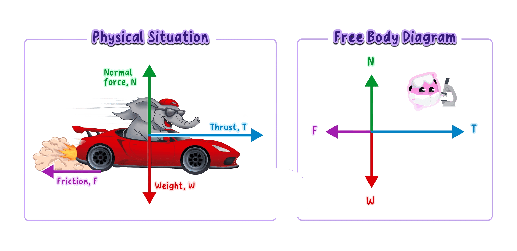
A free body force diagram is a diagram that shows only the forces acting on one chosen object, drawn as labelled arrows starting at that object.
- A free body force diagram strips a situation down to one object and shows every force acting on that object.
- The object is drawn as a simple box or a dot, and each force is drawn as an arrow starting on the object and pointing the way the force acts.
- Every arrow carries a label naming the force, and the lengths are drawn in proportion so the diagram shows at a glance whether the forces balance.
- Forces that the object exerts on other things are left out, because those forces act somewhere else.
- The forces most often needed are listed below.
- Weight, the gravitational force on the object, drawn vertically downwards from its centre of mass.
- Normal contact force, drawn at right angles to the surface the object rests on.
- Friction, drawn along the surface, opposing sliding.
- Tension, drawn along a rope, cable or spring, away from the object.
- Air resistance, or drag in a liquid, drawn opposite to the direction of motion through the fluid.
- Thrust, or the driving force, drawn in the direction in which an engine or motor pushes.
- Upthrust, drawn vertically upwards on an object floating or submerged in a fluid.
- A skydiver falling at a steady speed has just two arrows, weight downwards and air resistance upwards, and they are drawn the same length because the forces are balanced.
Forces on an isolated object or a system
- The motion of an object depends on the resultant force acting on it, not on any single force taken by itself.
- If the forces are unbalanced the resultant force is not zero, and the object accelerates in the direction of that resultant.
- If the forces are balanced the resultant force is zero, and this is the special case of equilibrium.
- A car on a level road has a forward driving force from the engine and backward resistive forces from friction and air resistance.
- While the driving force is larger than the total resistive force the car speeds up, and the difference between them is the resultant force.
- Air resistance grows as the car goes faster, so eventually the resistive forces match the driving force, the resultant becomes zero and the car settles at a steady top speed.
- A system of connected objects can be treated as one body, so a car towing a caravan can be drawn with a single weight, a single driving force and a single total resistive force.
- If the question asks for the force in the tow bar, the caravan has to be drawn on its own free body diagram, because the tension in the bar is then an external force acting on it.
Example
Resultant of two forces at right angles
- A box on a smooth floor is pulled by a force of 30 N30\ \text{N}30 N due east and a force of 40 N40\ \text{N}40 N due north.
- A scale of 1 cm=10 N1\ \text{cm} = 10\ \text{N}1 cm=10 N makes the two arrows 3.0 cm3.0\ \text{cm}3.0 cm and 4.0 cm4.0\ \text{cm}4.0 cm long.
- The 3.0 cm3.0\ \text{cm}3.0 cm arrow is drawn pointing east, and the 4.0 cm4.0\ \text{cm}4.0 cm arrow is drawn pointing north from its tip.
- The resultant is drawn from the tail of the first arrow to the tip of the second and measures 5.0 cm5.0\ \text{cm}5.0 cm.
- Converting with the scale gives 5.0 cm×10 N/cm=50 N5.0\ \text{cm} \times 10\ \text{N/cm} = 50\ \text{N}5.0 cm×10 N/cm=50 N.
- Measuring the angle between the resultant and the eastward arrow gives 53∘53^\circ53∘, so the resultant is 50 N50\ \text{N}50 N at 53∘53^\circ53∘ north of east.
Example
Resolving a rope force on a sledge
- A sledge is pulled by a rope with a force of 80 N80\ \text{N}80 N acting at 30∘30^\circ30∘ above the horizontal.
- Using a scale of 1 cm=20 N1\ \text{cm} = 20\ \text{N}1 cm=20 N, the rope force is drawn 4.0 cm4.0\ \text{cm}4.0 cm long at 30∘30^\circ30∘ to the horizontal.
- A rectangle is completed with this arrow as its diagonal, giving a horizontal side of 3.5 cm3.5\ \text{cm}3.5 cm and a vertical side of 2.0 cm2.0\ \text{cm}2.0 cm.
- The horizontal component is 3.5 cm×20 N/cm=70 N3.5\ \text{cm} \times 20\ \text{N/cm} = 70\ \text{N}3.5 cm×20 N/cm=70 N.
- The vertical component is 2.0 cm×20 N/cm=40 N2.0\ \text{cm} \times 20\ \text{N/cm} = 40\ \text{N}2.0 cm×20 N/cm=40 N.
- The horizontal component of 70 N70\ \text{N}70 N drags the sledge forwards, while the vertical component of 40 N40\ \text{N}40 N reduces the normal contact force from the snow.
Common Mistake
- Do not write that an object moving at a constant speed in a straight line has a forward resultant force, because a constant velocity means the resultant force is zero.
- Do not confuse no resultant force with no forces, since a book resting on a desk has two forces acting on it and a resultant of zero.
- Do not draw on a free body diagram any force that the object exerts on something else, because only forces acting on the chosen object belong there.
- Do not add force sizes as plain numbers when the forces act at an angle to each other, because only forces along the same line can be added arithmetically.
Exam technique
Marks in a scale drawing question
- Write the scale on the paper, because the examiner needs it to check the length of every arrow you have drawn.
- Use a sharp pencil, a ruler and a protractor, since one millimetre of error on a 1 cm=10 N1\ \text{cm} = 10\ \text{N}1 cm=10 N diagram is already a 10 N10\ \text{N}10 N error.
- Quote the resultant as a magnitude and a direction, and state the reference the angle has been measured from.
- Label every arrow on a free body diagram with the name of the force, because an unlabelled arrow earns nothing.
- Where the question says the object is at rest or moving at a constant velocity, open the answer by stating that the resultant force is zero.
Self review
- Describe how two forces acting at an angle are added using a scale vector diagram.
- State what the shape of a vector diagram looks like when the forces are in equilibrium.
- Explain what resolving a force into components means and name the two directions usually chosen.
- State the rule about which forces may appear on a free body force diagram.
- Explain why a car reaches a steady top speed even though the engine keeps providing a driving force.
