What a circuit diagram shows
Definition
Circuit diagram
A circuit diagram is a drawing of an electric circuit in which each component is shown by its standard symbol and the connecting wires are drawn as straight lines.
Definition
Component
A component is any single part of an electric circuit, such as a lamp, a resistor, a switch or a meter.
- A circuit diagram replaces a drawing of the real apparatus with an agreed symbol for each component, joined by straight lines that stand for the connecting wires.
- Every component has one standard symbol, so the same diagram can be read by anyone without a written explanation alongside it.
- A circuit diagram records how the components are connected to one another. It does not record where they sit on the bench, how long the leads are, or how large any object is.
- The diagram is never drawn to scale, so a small symbol may stand for a large piece of apparatus and a short straight line may stand for a long coiled lead.
Drawing conventions
- Draw every connecting wire as a straight line with a ruler, and turn every corner as a right angle rather than a curve.
- Bring each line squarely into the end of a symbol, so that it is obvious which two points of that symbol the wires are joined to.
- The circuit must form a complete loop with no gaps anywhere in the line, unless a switch has deliberately been drawn in its open position.
- A meeting point where three or more wires are joined is called a junction, and it is marked with a filled dot so that the join is unmistakable.
- Two lines that cross without a filled dot are read as not connected, so unnecessary crossings are best removed by redrawing the layout.
- No symbol is left with a line dangling from it, and no real component is given two symbols.
- Where labels are wanted, the name of the component is written beside its symbol and not inside it.
Note
- A filled dot where lines meet means the wires are joined at that point.
- Two lines crossing with no dot means the wires simply pass over one another.
- Leaving the dot off a genuine junction changes the circuit that the diagram describes.
Cells and batteries
Definition
Cell
A cell is a single source of potential difference that uses a chemical reaction to push charge around a circuit.
Definition
Battery
A battery is two or more cells joined together in series so that their potential differences add.
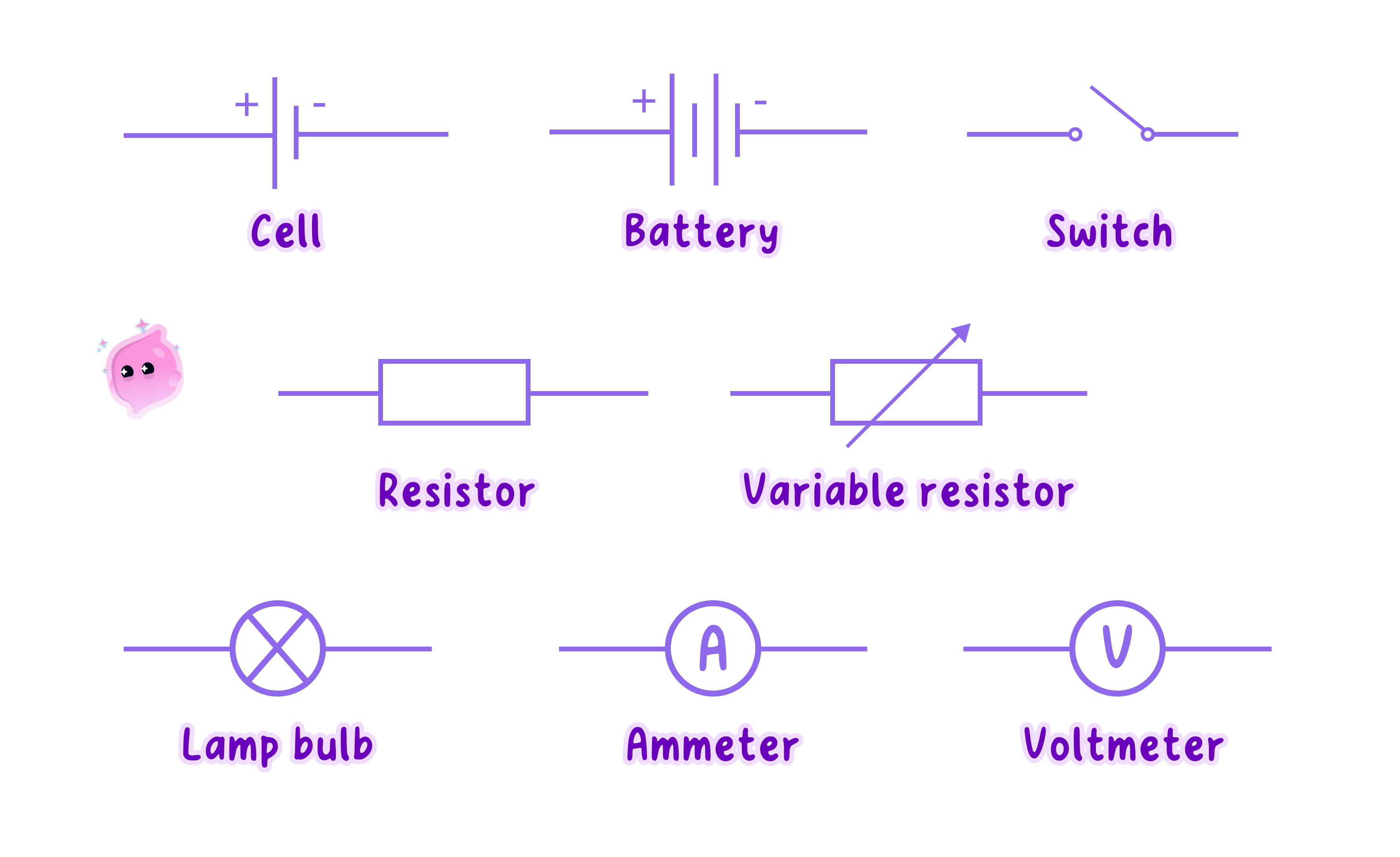
- The symbol for a cell is a pair of parallel lines drawn across a break in the wire: one long thin line and one short thick line.
- The long thin line stands for the positive terminal and the short thick line stands for the negative terminal.
- A battery is two or more cells joined end to end, so its symbol is simply the cell symbol repeated in a row with a small gap between each pair of lines.
- Every cell in a battery symbol faces the same way, with all of the long thin lines on the same side, because the cells are meant to push in the same direction round the loop.
- One cell drawn the wrong way round describes a different circuit from the one intended, so the orientation of the lines is part of the answer and not decoration.
Key Idea
In every cell and battery symbol the long thin line marks the positive terminal.
Symbols to recognise
- A switch is drawn as two contacts in a break in the line: it is open when the moving contact is lifted away from the second contact, and closed when it lies flat and bridges the gap.
- A filament lamp is a circle with a cross inside it, and a fixed resistor is a plain rectangle with nothing inside it.
- A variable resistor is the same rectangle with an arrow drawn diagonally across it, and a fuse is a rectangle with a line running through it from one side to the other.
- An ammeter is a circle containing the letter A\text{A}A and a voltmeter is a circle containing the letter V\text{V}V.
- A diode is a solid triangle pointing at a short bar, with the point of the triangle showing the single direction in which the diode allows charge through, and a light-emitting diode is that same symbol with two small arrows pointing away from it.
- A light-dependent resistor is a resistor rectangle inside a circle with two arrows pointing in towards it, and a thermistor is a resistor rectangle with a line drawn across it that bends upwards at one end.
- A motor is a circle containing the letter M\text{M}M and a generator is a circle containing the letter G\text{G}G.
- A loudspeaker is a small rectangle with a cone opening outwards from one side, and a thermocouple is drawn as two lines of different metals meeting at a single point.
Switches and meters
- A switch drawn in the single loop of a circuit controls the whole loop, because opening it breaks the only path the wires provide.
- An ammeter is always drawn as part of the loop itself, so the line runs into one side of the circle and out of the other side.
- A voltmeter is always drawn on its own short branch, with the line leaving the loop just before the component and rejoining it just after, so that the meter sits across that component.
- Drawn in that way, the voltmeter and the component enclose a small loop of their own on the page, which is how a reader recognises the connection at a glance.
Common Mistake
- Do not draw an ammeter on a side branch. Its symbol belongs in the loop, with the line passing straight through it.
- Do not draw a voltmeter in the loop. Its symbol belongs on a branch across the named component.
- Do not leave a gap where the line should continue, because a gap describes a broken circuit rather than a tidy drawing.
- Do not treat two crossing lines as joined. Only a filled dot shows a junction.
- Do not sketch the real appearance of a component, such as a coil of wire in place of the plain rectangle of a fixed resistor.
From apparatus to diagram
- Begin by listing every real object shown in the photograph or named in the description, and write the symbol that stands for each one beside it.
- Choose one terminal of the supply and trace the leads by hand all the way round to the other terminal, noting each component in the order it is met.
- Draw the loop as a plain rectangle first, then place the symbols along its sides in that same order, spacing them out so each one is clear.
- Represent every lead, crocodile clip and terminal block as a plain straight line, since none of them has a symbol of its own.
- Finish by checking the finished drawing back against the list, so that no component has been left out and none has been invented.
Exam technique
Drawing a circuit accurately
- Use a ruler and a sharp pencil, and draw the wires as straight lines with right-angled corners.
- Check that the loop closes before moving on, since an accidental gap costs the mark even when every symbol is correct.
- Put a filled dot at every point where three or more wires meet.
- Show a switch in the position the question describes, open or closed, rather than choosing one at random.
- Where a meter is asked for, place the ammeter in the loop and the voltmeter across the component that the question names.
Self review
- Draw the symbols for a cell, a battery, a fixed resistor and a variable resistor.
- State which line of a cell symbol represents the positive terminal.
- Explain what a filled dot at a meeting point of wires tells the reader.
- Name the components whose symbols are circles containing A\text{A}A, V\text{V}V, M\text{M}M and G\text{G}G.
- Describe where an ammeter and a voltmeter are drawn in a circuit diagram.
