5.4.1a Moments and the principle of moments
Forces can cause rotation
Definition
Pivot
A pivot is the point about which an object turns.
- A force can make an object rotate if it acts at a distance from a pivot.
- Examples include pushing a door handle so the door turns about its hinges, pressing one side of a seesaw, turning a nut with a spanner, and pushing a bicycle pedal so it turns about its axle.
- In each case the object rotates because the force does not act through the pivot; the further the force acts from the pivot, the greater the turning effect.
Moment of a force
Definition
Moment of a force
The moment of a force is the turning effect of the force.
- The size of the moment depends on the size of the force and the perpendicular distance from the pivot to the line of action of the force.
- The equation is M=FdM = FdM=Fd.
- MMM is the moment in newton-metres (Nm\text{Nm}Nm).
- FFF is the force in newtons (N\text{N}N).
- ddd is the perpendicular distance from the pivot to the line of action of the force, in metres (m\text{m}m).
- A larger force or a larger perpendicular distance gives a larger moment.
Example
- A student pushes down on the end of a spanner with a force of 40 N40\ \text{N}40 N. The perpendicular distance from the pivot to the line of action of the force is 0.25 m0.25\ \text{m}0.25 m. Calculate the moment of the force.
- Write the equation: M=FdM = FdM=Fd.
- Substitute the values: M=40 N×0.25 mM = 40\ \text{N} \times 0.25\ \text{m}M=40 N×0.25 m.
- Calculate the moment: M=10 NmM = 10\ \text{Nm}M=10 Nm.
Clockwise and anticlockwise moments
- A moment can act clockwise or anticlockwise about a pivot.
- On a seesaw, a force on the left side may cause an anticlockwise moment.
- A force on the right side may cause a clockwise moment.
- If the object is balanced it does not rotate, so the clockwise and anticlockwise turning effects are equal.
Key Idea
- For a balanced object, the total clockwise moment about a pivot equals the total anticlockwise moment about that pivot.
- This is the principle of moments.
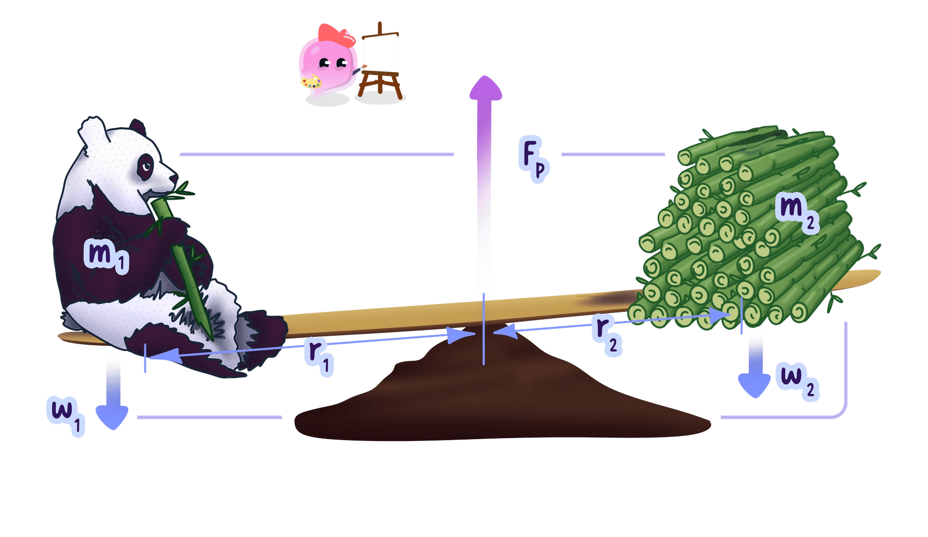
Balancing on a pivot
- The word total matters: add all clockwise moments together and all anticlockwise moments together.
- You may be asked to find an unknown force or distance for a balanced object; set the total clockwise moment equal to the total anticlockwise moment and rearrange M=FdM = FdM=Fd as needed (d=MFd = \dfrac{M}{F}d=FM).
Example
- A plank is balanced on a pivot. A child exerts a downward force of 300 N300\ \text{N}300 N at 1.2 m1.2\ \text{m}1.2 m from the pivot on the left. Another child sits 2.0 m2.0\ \text{m}2.0 m from the pivot on the right. Calculate the force exerted by the second child.
- Apply the principle of moments: clockwise moment = anticlockwise moment.
- Anticlockwise moment from the first child: M=300 N×1.2 m=360 NmM = 300\ \text{N} \times 1.2\ \text{m} = 360\ \text{Nm}M=300 N×1.2 m=360 Nm.
- The plank is balanced, so the clockwise moment is also 360 Nm360\ \text{Nm}360 Nm: 360 Nm=F×2.0 m360\ \text{Nm} = F \times 2.0\ \text{m}360 Nm=F×2.0 m.
- Rearrange: F=360 Nm2.0 mF = \dfrac{360\ \text{Nm}}{2.0\ \text{m}}F=2.0 m360 Nm.
- Calculate the force: F=180 NF = 180\ \text{N}F=180 N.
Common Mistake
- Do not automatically use the length of the object as the distance in M=FdM = FdM=Fd.
- The distance must be the perpendicular distance from the pivot to the line of action; a force acting straight through the pivot has a moment of zero.
- The unit of a moment is Nm\text{Nm}Nm, not N/m\text{N/m}N/m.
Exam technique
- Write the equation first, M=FdM = FdM=Fd, and check the distance is in metres.
- For balanced objects, set the total clockwise moment equal to the total anticlockwise moment.
- Give the correct unit (Nm\text{Nm}Nm for a moment, N\text{N}N for a force, m\text{m}m for a distance) and, in explanations, use the words clockwise, anticlockwise, pivot and balanced.
- A moment can be used to find a distance too: rearranging M=FdM = FdM=Fd gives d=MFd = \dfrac{M}{F}d=FM, so a 15 Nm15\ \text{Nm}15 Nm moment from a 50 N50\ \text{N}50 N force acts at 0.30 m0.30\ \text{m}0.30 m from the pivot.
Self review
- What is the moment of a force?
- State the equation for a moment and its units.
- Which distance is used in M=FdM = FdM=Fd?
- State the principle of moments.
- Why does a force acting through the pivot produce no turning effect?
5.4.1b Levers and gears
Transmitting rotational effects
Definition
Rotational effect of a force
The turning effect produced when a force makes, or tends to make, an object rotate about a pivot or axis.
- To transmit a rotational effect means to transfer a turning effect from one part of a system to another.
- Simple levers and gear systems can both do this.
Levers
Definition
Lever
A lever is a rigid bar that can rotate about a fixed point called a pivot.
- When an input force is applied to one part of a lever, it produces a rotational effect about the pivot.
- Because the lever is rigid, its rotation transfers this effect to another part of the lever.
- Pushing down on one end of a seesaw makes it rotate about the central pivot, so as one end moves down the other moves up, transmitting the rotational effect from one side of the pivot to the other.
- A lever system has three important parts.
- The effort, which is the input force applied to the lever.
- The pivot, about which the lever rotates.
- The load, which is moved by the output force from the lever.
- Examples of simple levers include seesaws, crowbars and handles.
Gears
Definition
Gear
A gear is a toothed wheel that rotates about an axis; a simple gear system has gears whose teeth interlock.
- One gear is turned by an input force: the driving gear.
- As it rotates, its teeth push against the teeth of the second, driven gear, and the force between the teeth produces a rotational effect on it.
- The gears therefore transmit the rotational effect from one rotating axis to another.
- Two interlocking gears rotate in opposite directions, because the driving gear’s teeth push the driven gear’s teeth in the opposite direction at their point of contact.
Key Idea
- In a lever, the rigid bar transmits the rotational effect through the pivot.
- In a gear system, the forces between interlocking teeth transmit the rotational effect from one gear to another.
Explaining how gears transmit rotation
- For an “explain how” question, give a linked sequence rather than just naming the device.
Exam technique
- For a lever, link the steps: input force gives a rotation about the pivot, and the rigid bar transmits that effect to the load.
- For gears, link the steps: the driving gear rotates, its teeth exert a force on the driven gear, and the driven gear rotates the opposite way.
- Do not say two interlocking gears rotate the same way; they rotate in opposite directions.
- Do not describe a lever as simply “making the force bigger”; explain how the input force causes rotation about the pivot and how the rigid bar transmits that effect to the load.
Self review
- What is meant by the rotational effect of a force?
- What fixed point does a lever rotate about?
- How does a rigid lever transmit a rotational effect to a load?
- How do the teeth of a driving gear make a driven gear rotate?
- In which directions do two interlocking gears rotate?
