Revision notes for AQA GCSE Computer Science Boolean logic. Open the guide for explanations and worked examples. Written against the AQA GCSE Computer Science (8525) specification, so the content matches what's examinable rather than general Computer Science background.
Boolean logic
What you'll learn
- How the NOT, AND, OR and XOR logic gates work.
- How to build truth tables for gates and simple circuits.
- How to read and create simple logic circuit diagrams.
- How to write and interpret Boolean expressions using AQA notation.
Boolean logic starts with 0 and 1
Computers use binary values: 0 and 1. In Boolean logic, these are treated as logical values:
- 0 means False, No, or Off
- 1 means True, Yes, or On
Boolean logic is useful because computer systems often need to make decisions from conditions, such as:
- Is the password correct?
- Is the temperature too high?
- Are both buttons being pressed?
Definition
Boolean logic
Boolean logic is a system of logic where every value is either 0 or 1, and logic operations are used to produce an output from one or more inputs.
Logic gates
A logic gate is a circuit component that takes one or more binary inputs and produces one binary output.
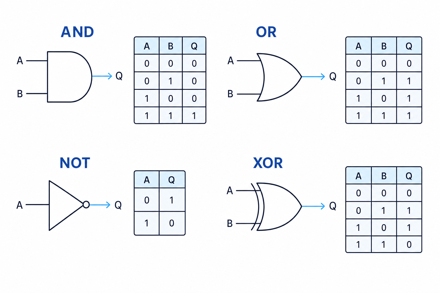
For GCSE Computer Science, you need to know four gates: NOT, AND, OR and XOR. You do not need NAND or NOR gates for this topic.
Here are the symbols and truth tables for the four gates.
Definition
Truth table
A truth table shows every possible combination of input values and the output produced for each combination.
The NOT gate
The NOT gate has one input and one output. It reverses the input:
- If the input is 0, the output is 1.
- If the input is 1, the output is 0.
| A | Q |
|---|---|
| 0 | 1 |
| 1 | 0 |
Key Idea
NOT means invert
A NOT gate flips a value to its opposite: 0 becomes 1, and 1 becomes 0.
The AND gate
The AND gate has two inputs. It outputs 1 only when both inputs are 1.
| A | B | Q |
|---|---|---|
| 0 | 0 | 0 |
| 0 | 1 | 0 |
| 1 | 0 | 0 |
| 1 | 1 | 1 |
Think of AND as a strict gate: both conditions must be true.
The OR gate
The OR gate has two inputs. It outputs 1 when at least one input is 1.
| A | B | Q |
|---|---|---|
| 0 | 0 | 0 |
| 0 | 1 | 1 |
| 1 | 0 | 1 |
| 1 | 1 | 1 |
OR is less strict than AND: one true input is enough.
The XOR gate
The XOR gate means exclusive OR. It outputs 1 when exactly one input is 1.
| A | B | Q |
|---|---|---|
| 0 | 0 | 0 |
| 0 | 1 | 1 |
| 1 | 0 | 1 |
| 1 | 1 | 0 |
Common Mistake
OR and XOR are different
OR outputs 1 when both inputs are 1. XOR outputs 0 when both inputs are 1, because XOR means exactly one input must be 1.
Example
Choosing a gate from a condition
A security light should turn on only when motion is detected and it is dark outside. Input M means “motion detected” and input D means “dark outside”.
- The word and tells you both conditions must be true: motion must be detected, and it must be dark.
- The gate that outputs 1 only when both inputs are 1 is the AND gate.
- The output can be written as the Boolean expression M.DM . DM.D.
Constructing truth tables
For a truth table, you must include every possible combination of inputs.
For nnn inputs, the number of rows is 2n2^n2n.
So:
- 1 input gives 2 rows.
- 2 inputs give 4 rows.
- 3 inputs give 8 rows.
In this GCSE topic, truth tables will contain up to three inputs.
Listing combinations neatly
For three inputs, use a consistent order like this:
| A | B | C |
|---|---|---|
| 0 | 0 | 0 |
| 0 | 0 | 1 |
| 0 | 1 | 0 |
| 0 | 1 | 1 |
| 1 | 0 | 0 |
| 1 | 0 | 1 |
| 1 | 1 | 0 |
| 1 | 1 | 1 |
Tip
Use binary order
List input combinations in binary counting order. This helps you avoid missing or repeating a row.
Combining gates into circuits
A logic circuit is made by connecting logic gates together. The output of one gate can become the input to another gate.
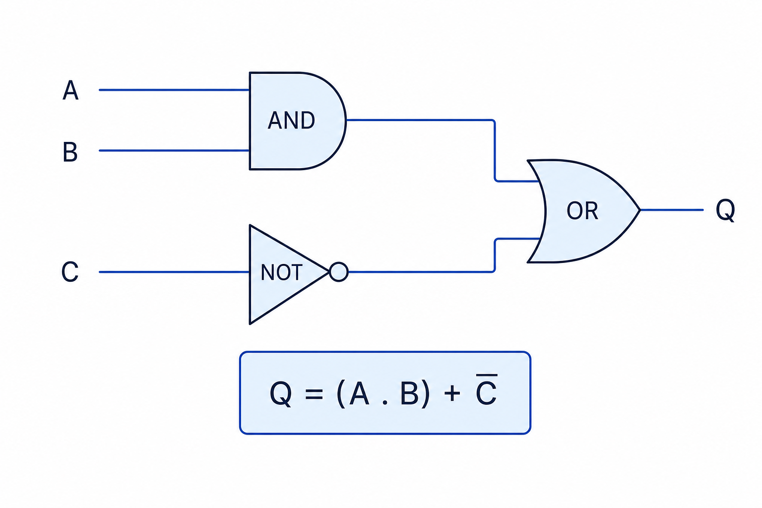
This circuit takes three inputs. A and B go into an AND gate. C goes into a NOT gate. The results are then combined using an OR gate.
Example
Constructing a truth table for a circuit
For the circuit above, find the output Q for every input combination.
- There are three inputs, A, B and C, so the truth table needs 8 rows.
- Work out the AND gate first. The column “A AND B” is 1 only when A=1A = 1A=1 and B=1B = 1B=1.
- Work out the NOT gate next. The column “NOT C” flips C, so 0 becomes 1 and 1 becomes 0.
- Use the final OR gate. Q is 1 if either “A AND B” is 1 or “NOT C” is 1.
| A | B | C | A AND B | NOT C | Q |
|---|---|---|---|---|---|
| 0 | 0 | 0 | 0 | 1 | 1 |
| 0 | 0 | 1 | 0 | 0 | 0 |
| 0 | 1 | 0 | 0 | 1 | 1 |
| 0 | 1 | 1 | 0 | 0 | 0 |
| 1 | 0 | 0 | 0 | 1 | 1 |
| 1 | 0 | 1 | 0 | 0 | 0 |
| 1 | 1 | 0 | 1 | 1 | 1 |
| 1 | 1 | 1 | 1 | 0 | 1 |
Key Idea
Use intermediate columns
For a circuit with several gates, do not try to jump straight to the final answer. Add one column for each gate output, then combine them step by step.
Interpreting truth tables
To interpret a truth table, look for the rows where the output is 1. These rows tell you the conditions that make the circuit “true”.
Example
Interpreting a truth table
Using the truth table from the previous example:
- Notice that every row where C is 0 gives output Q as 1. This happens because NOT C becomes 1.
- Look at the rows where C is 1. In these rows, NOT C is 0, so the circuit depends on A AND B.
- The only row where C is 1 and Q is still 1 is when A and B are both 1.
- So the circuit outputs 1 when C is 0, or when A and B are both 1.
Boolean expressions
A Boolean expression is a written version of a logic circuit.
In AQA notation:
- AND is written using a dot, for example A.BA . BA.B
- OR is written using a plus sign, for example A+BA + BA+B
- XOR is written using the ⊕ symbol, for example A⊕BA \oplus BA⊕B
- NOT is written using an overbar, for example Aˉ\bar{A}Aˉ
Definition
Boolean expression
A Boolean expression represents a logic circuit using symbols instead of drawing gates.
For example:
(A.B)+Cˉ(A . B) + \bar{C}(A.B)+Cˉ
means:
- A AND B
- OR
- NOT C
So it matches the circuit shown earlier.
Common Mistake
Overbar range
The overbar only applies to the part underneath it. Aˉ+B\bar{A} + BAˉ+B means NOT A, then OR B. But A+B‾\overline{A + B}A+B means do A OR B first, then NOT the result.
Writing an expression from a circuit
When turning a circuit into a Boolean expression, work from left to right.
Example
Writing an expression from a circuit
For the circuit with inputs A, B and C shown above:
- The top gate combines A and B using AND, so that part is A.BA . BA.B.
- The lower gate applies NOT to C, so that part is Cˉ\bar{C}Cˉ.
- The final gate is OR, so combine the two parts with plus.
- The full expression is Q=(A.B)+CˉQ = (A . B) + \bar{C}Q=(A.B)+Cˉ.
Drawing a circuit from an expression
When turning a Boolean expression into a circuit, break it into smaller parts.
Start with anything inside brackets or under an overbar. Then connect those results using the final operator.
Example
Drawing a circuit from an expression
Draw the circuit for Q=(A+B).CˉQ = (A + B) . \bar{C}Q=(A+B).Cˉ.
- The brackets A+BA + BA+B mean A and B must go into an OR gate.
- The overbar Cˉ\bar{C}Cˉ means C must go into a NOT gate.
- The dot means the result of the OR gate and the result of the NOT gate must go into an AND gate.
- The output of that final AND gate is Q.
Tip
Brackets make the order clear
Use brackets in Boolean expressions to show which gate happens first. This is especially helpful when a circuit has more than one gate.
Exam technique
In the exam
- For truth tables, list the input combinations in order and add one intermediate column for each gate.
- For circuit diagrams, work left to right and label each gate’s output before moving on.
- For Boolean expressions, copy the operator symbols carefully: dot for AND, plus for OR, ⊕ for XOR and overbar for NOT.
Self review
Check yourself
- What is the only input combination that makes an AND gate output 1?
- Why does XOR output 0 when both inputs are 1?
- For Q=(A+B).CˉQ = (A + B) . \bar{C}Q=(A+B).Cˉ, which gates would you draw before the final gate?

Recap questions
Test yourself with 5 quick questions on this guide. Answer them all correctly to complete it.
You've reached the end
Test yourself on this topic, or move on to the next guide.
How was this guide?