Figure 1 shows a logic circuit diagram with three inputs, labeled A, B, and C, and two logic gates, labeled Gate 1 and Gate 2.
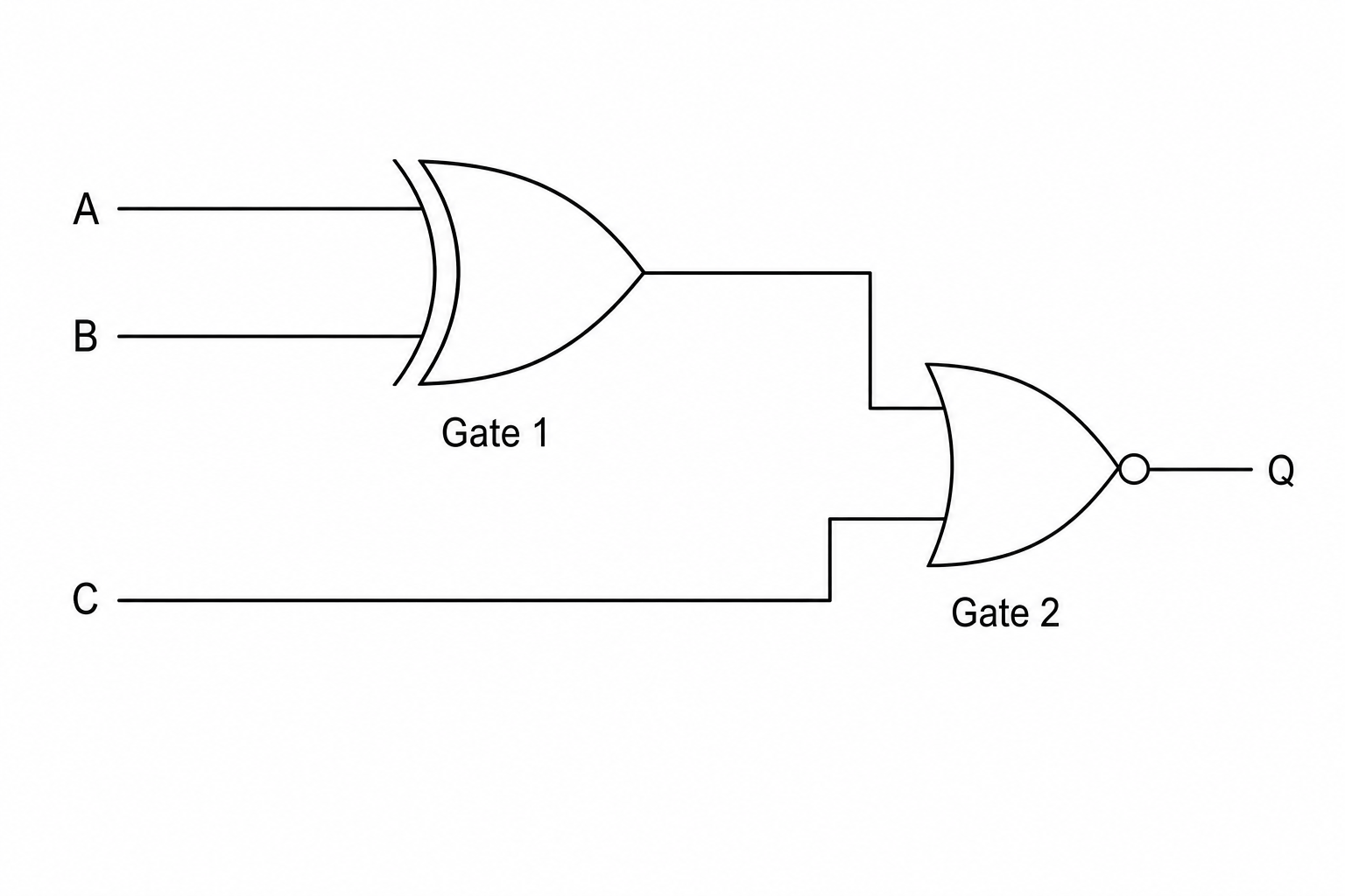
State the name of the logic gate used at Gate 2 in Figure 1.
Boolean logic Questions
Practise AQA GCSE Computer Science Boolean logic with exam-style questions for GCSE Computer Science. 83 questions, matched to the AQA GCSE Computer Science (8525) specification and written in Paper 1 and Paper 2 style. Every question includes a full worked solution and mark scheme, so you can see where marks are awarded rather than just whether you got the answer right.