A logic circuit is designed to implement the Boolean expression:
Output X=(A AND B) OR (NOT B) \text{Output } X = (A \text{ AND } B) \text{ OR } (\text{NOT } B) Output X=(A AND B) OR (NOT B)The diagram in Figure 1 shows this circuit where the actual gates have been replaced by generic boxes labeled Gate 1, Gate 2, and Gate 3.
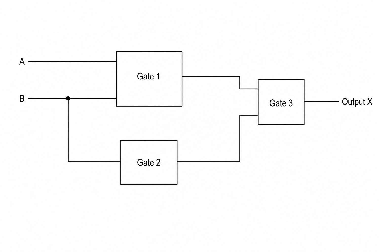
Draw the standard logic circuit symbol for the logic gate that must be used at Gate 3 to correctly implement the expression.
Boolean logic Questions
Practise AQA GCSE Computer Science Boolean logic with exam-style questions for GCSE Computer Science. 83 questions, matched to the AQA GCSE Computer Science (8525) specification and written in Paper 1 and Paper 2 style. Every question includes a full worked solution and mark scheme, so you can see where marks are awarded rather than just whether you got the answer right.