Superposition
What you'll learn
- How to use the principle of superposition to add waves graphically.
- What interference, coherence, path difference and phase difference mean.
- How to predict constructive and destructive interference.
- How double slits and diffraction gratings are used to measure the wavelength of light.
Before superposition: the wave ideas you need
A displacement is the distance and direction of a point on a wave from its equilibrium position. For a transverse wave, this is drawn “up” or “down” on the page. For sound, you might instead represent pressure variation or particle displacement.
The amplitude is the maximum displacement from equilibrium. The wavelength, λ\lambdaλ, is the distance between two adjacent points in phase, such as crest to crest. The frequency, fff, is the number of complete cycles per second, measured in hertz, Hz.
Phase describes where a wave is in its cycle. Two points are in phase if they are at the same stage of the cycle; they rise and fall together.
The principle of superposition
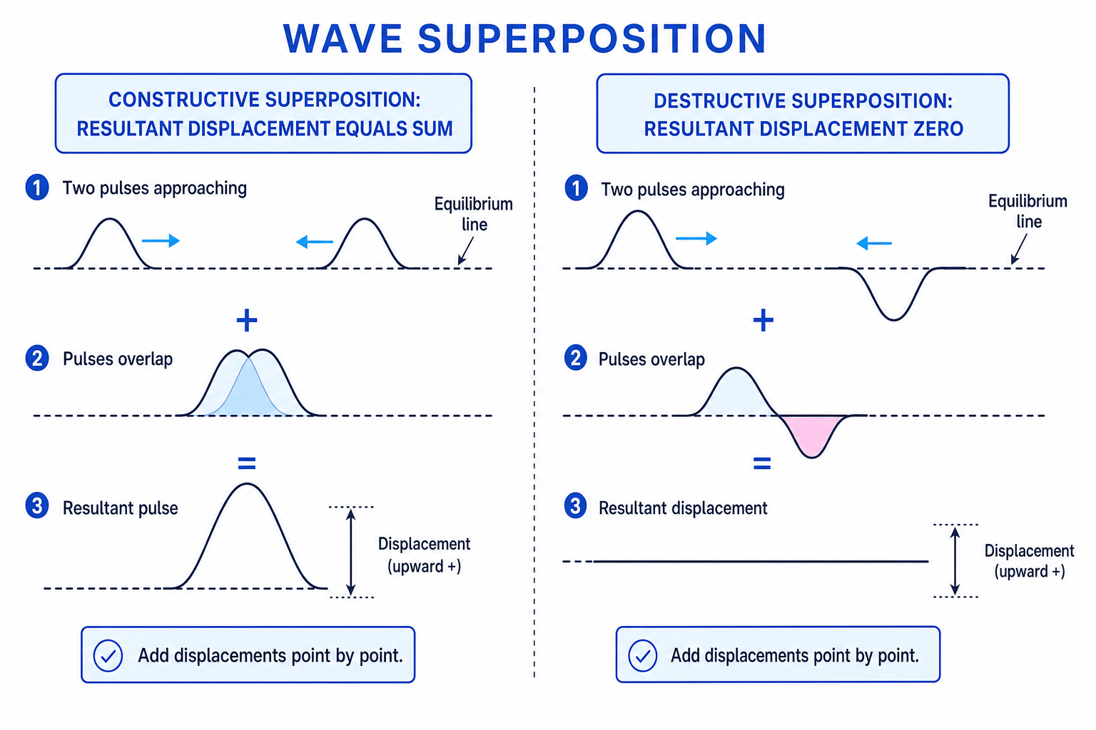
When waves overlap, the medium does not “choose” one wave. The displacements combine.
Principle of superposition
When two or more waves meet at a point, the resultant displacement is the vector sum of the individual displacements at that point.
For waves drawn on a displacement graph, “vector sum” usually means you add upward displacements as positive and downward displacements as negative.
What actually adds
In superposition, you add displacements point by point, not intensities, loudnesses or brightnesses directly.
Adding displacements
At one instant, two waves overlap at point P. Wave 1 has displacement +3.0 mm and wave 2 has displacement -1.2 mm. At point Q, wave 1 has displacement +2.0 mm and wave 2 has displacement +1.5 mm. Find the resultant displacement at each point.
-
Choose a sign convention. Take upward displacement as positive, so downward displacement is negative.
-
At P, add the signed displacements:
- At Q, both displacements are positive, so they reinforce:
- P shows partial cancellation; Q shows reinforcement.
Graphical superposition
A graphical method means drawing or reading the displacement of each wave at the same position and time, then adding the vertical displacements.
For two transverse waves:
- crest plus crest gives a larger crest;
- trough plus trough gives a deeper trough;
- crest plus equal trough gives zero displacement;
- unequal opposite displacements give partial cancellation.
This same idea works for all waves, but the quantity on the vertical axis may change. For sound, you might graph pressure variation against position. For microwaves or light, you often think in terms of the oscillating electric field.
Interference, coherence, path difference and phase difference
Interference is the pattern produced when waves superpose, giving regions of large and small resultant amplitude.
Key interference terms
- Coherent sources have the same frequency and a constant phase difference.
- Path difference, Δs\Delta sΔs, is the difference in distance travelled by two waves reaching the same point.
- Phase difference, ϕ\phiϕ, is the difference between the stages of the two waves’ cycles, usually measured in radians.
For waves from coherent sources that started in phase, path difference and phase difference are linked by:
ϕ=2πΔsλ \phi = \frac{2\pi \Delta s}{\lambda} ϕ=λ2πΔsSo a path difference of one whole wavelength means a phase difference of 2π2\pi2π rad. A path difference of half a wavelength means a phase difference of π\piπ rad.
Constructive and destructive interference
Constructive interference occurs when waves arrive in phase and reinforce. Destructive interference occurs when waves arrive in antiphase and cancel as much as possible.
Interference conditions
For coherent sources initially in phase: constructive interference occurs when Δs=nλ\Delta s = n\lambdaΔs=nλ, giving ϕ=2nπ\phi = 2n\piϕ=2nπ. Destructive interference occurs when Δs=(n+12)λ\Delta s = \left(n + \frac{1}{2}\right)\lambdaΔs=(n+21)λ, giving ϕ=(2n+1)π\phi = (2n+1)\piϕ=(2n+1)π, where nnn is an integer.
Classifying interference from path difference
Two coherent microwave sources emit waves of wavelength 3.0 cm. At a detector, the distances from the two sources are 42.0 cm and 49.5 cm. Decide whether the interference is constructive or destructive.
- Calculate the path difference:
- Compare this with the wavelength:
-
A path difference of 2.5 wavelengths is a half-integer multiple of λ\lambdaλ, so the waves arrive in antiphase.
-
Therefore the interference is destructive.
Adding amplitudes instead of displacements
Do not say “large amplitude plus large amplitude always gives constructive interference”. You must consider phase: equal amplitudes can cancel completely if they arrive in antiphase.
Two-source interference with sound and microwaves
For two-source interference, you need two coherent sources. In a lab, this is usually achieved by driving both sources from the same oscillator or signal generator.
For sound, two loudspeakers can be connected to the same signal generator. As you move a microphone or your ear across the room, you detect loud regions and quiet regions. These are caused by constructive and destructive interference of sound waves.
For microwaves, a transmitter can illuminate two slits, or two microwave sources can be fed coherently. A microwave receiver is moved along a line to find maxima and minima in signal strength.
Practical reality
A “minimum” may not be zero because the two waves may not have equal amplitude, and reflections from walls or metal objects can create extra interference.
Young’s double-slit experiment
In Young’s double-slit experiment, visible light passes through two narrow slits. The slits act as two coherent sources because the light reaching them comes from the same original wavefront.
A fringe is a bright or dark band in the interference pattern. Bright fringes occur where light from the two slits arrives in phase. Dark fringes occur where it arrives in antiphase.
Young’s result was historically important because a stable interference pattern is strong classical evidence for the wave nature of light. It supported Huygens’ wave model over Newton’s corpuscular, or particle, model of light.
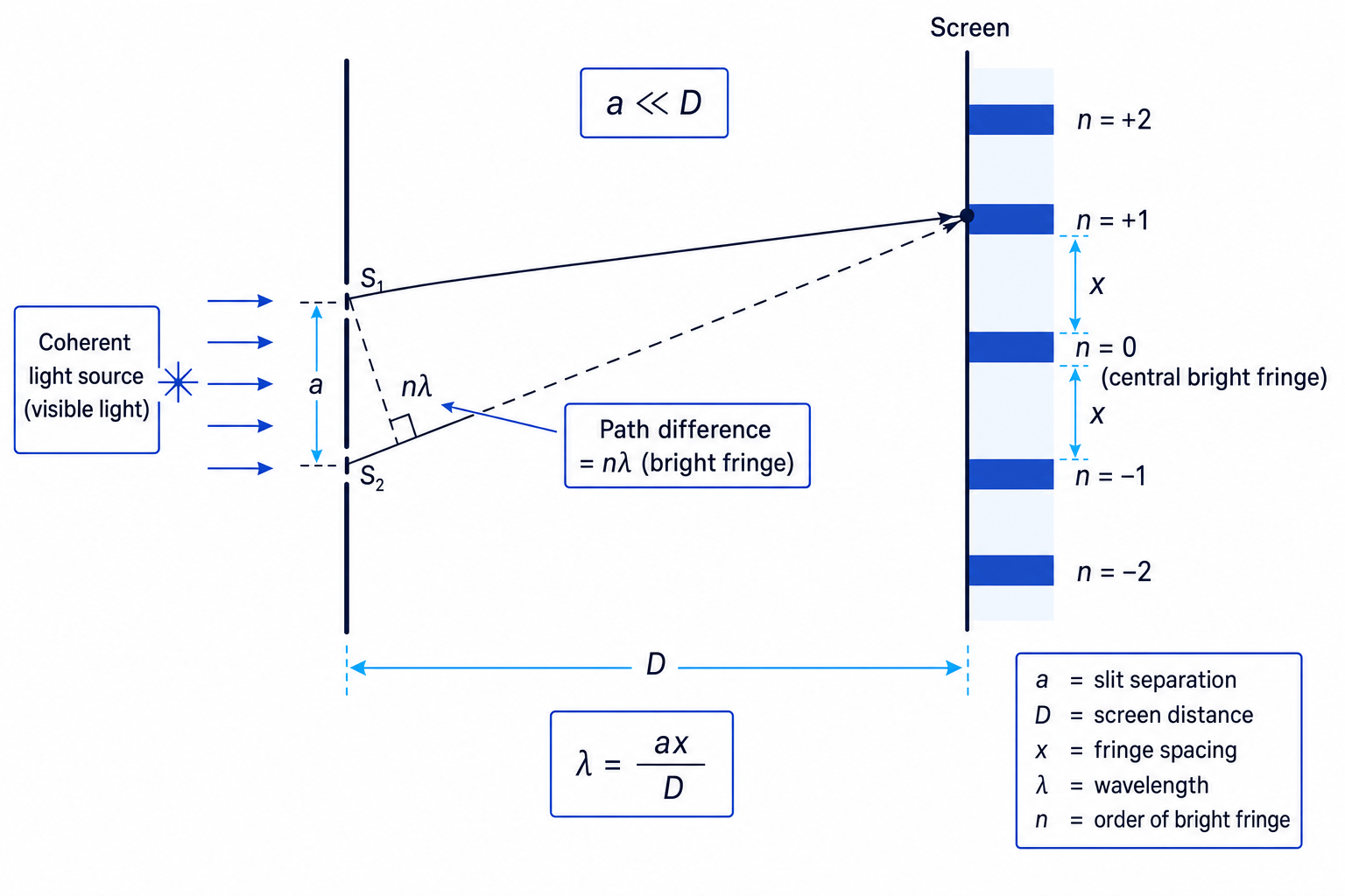
For a double slit:
λ=axD \lambda = \frac{ax}{D} λ=Daxwhere:
- λ\lambdaλ is the wavelength;
- aaa is the slit separation;
- xxx is the fringe spacing between adjacent bright fringes;
- DDD is the distance from the slits to the screen.
This equation is valid when a≪Da \ll Da≪D, so the rays to the screen are almost parallel and the small-angle approximation is reasonable.
Finding wavelength using a double slit
A laser shines through two slits separated by 0.250 mm. The screen is 2.00 m from the slits. The distance across 10 fringe spacings is 42.0 mm. Calculate the wavelength of the light.
- Find the spacing for one fringe:
- Convert the slit separation into metres:
- Substitute into the double-slit equation:
- Calculate and quote the result:
This is 525 nm, which is in the visible region.
Measuring fringe spacing
Measure across many fringe spacings, then divide by the number of spaces. This reduces the percentage uncertainty in xxx compared with measuring just one spacing.
Determining wavelength using a diffraction grating
A diffraction grating has many equally spaced slits. The spacing between adjacent slits is ddd. A grating produces sharp bright maxima at particular angles.
For normal incidence:
dsinθ=nλ d \sin \theta = n\lambda dsinθ=nλwhere:
- ddd is the grating spacing;
- θ\thetaθ is the angle from the normal to the bright maximum;
- nnn is the order number;
- λ\lambdaλ is the wavelength.
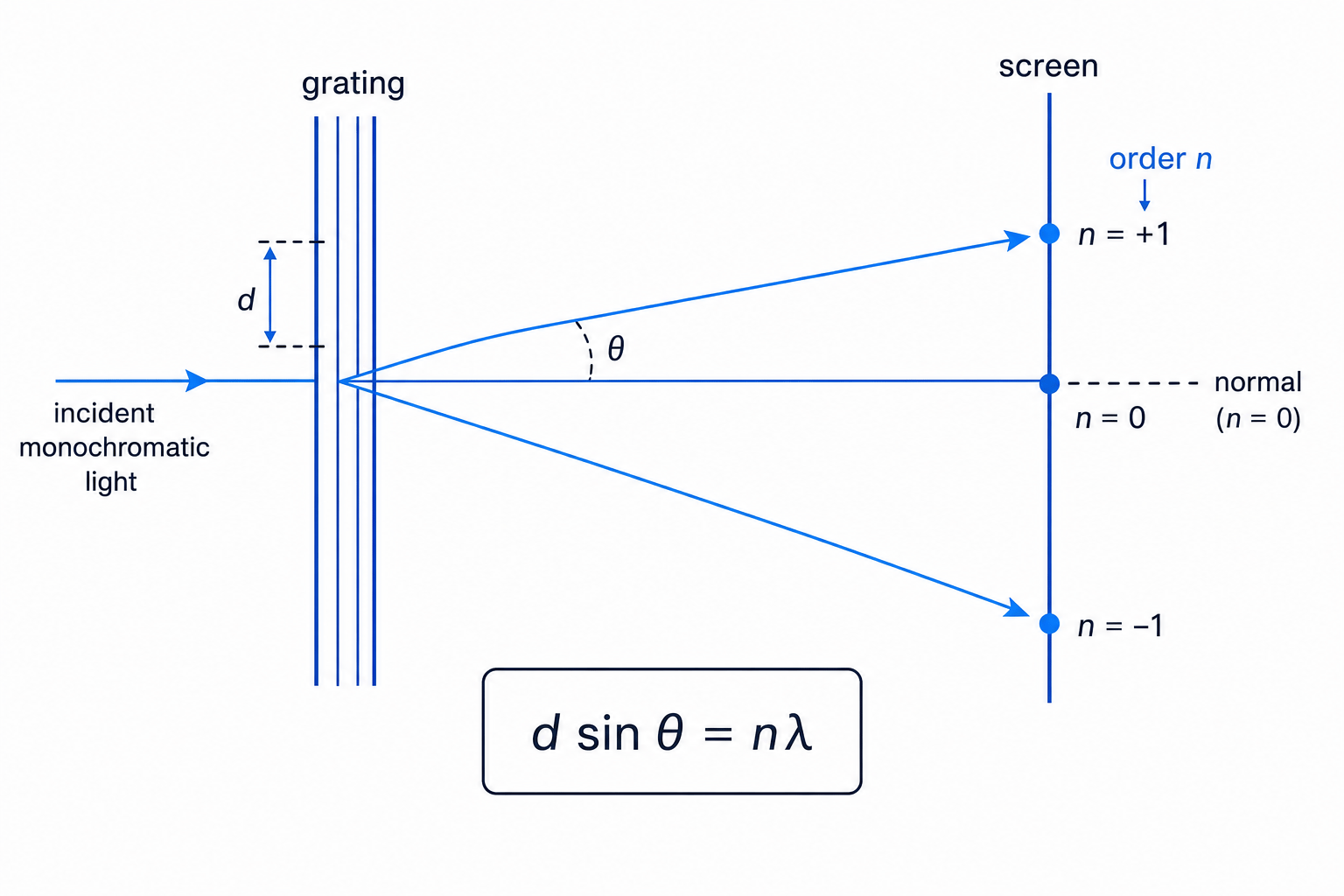
In practice, use monochromatic light, meaning light of one wavelength. Measure the angle to a first-order or second-order maximum using a spectrometer, or use a screen and geometry to find the angle. If the grating has NNN lines per metre, then:
d=1N d = \frac{1}{N} d=N1Finding wavelength using a diffraction grating
A diffraction grating has 600 lines per millimetre. The first-order maximum is observed at an angle of 18.0° from the normal. Calculate the wavelength of the light.
- Convert the line density into lines per metre:
- Find the slit spacing:
- Use dsinθ=nλd \sin \theta = n\lambdadsinθ=nλ with first order, so n=1n = 1n=1:
- Calculate the wavelength:
This is 515 nm, a visible wavelength.
In the exam
- Start by deciding whether the question is about adding displacements, path difference, a double slit, or a diffraction grating.
- For interference conditions, compare Δs\Delta sΔs with λ\lambdaλ: whole-number multiples give constructive interference; half-integer multiples give destructive interference.
- For double-slit calculations, use λ=axD\lambda = \frac{ax}{D}λ=Dax only when a≪Da \ll Da≪D, and convert millimetres or nanometres into metres before substituting.
- For diffraction gratings, convert line density into spacing using d=1Nd = \frac{1}{N}d=N1, then use dsinθ=nλd \sin \theta = n\lambdadsinθ=nλ.
- In practical questions, mention measuring over many fringes or using symmetric orders to reduce uncertainty.
Check yourself
- Why must two sources be coherent to produce a stable interference pattern?
- A detector is moved from a maximum to the next maximum. What path-difference change has occurred?
- In a grating experiment, why must “600 lines per millimetre” be converted before calculating ddd?