A small thin rectangular slice of a doped p-type semiconductor wafer has width www and thickness ttt and carries a constant current III. The current is due to the movement of positive charge carriers (holes), each carrying a charge of +e+e+e and having a mean drift velocity vvv.
A uniform magnetic field of flux density BBB is directed vertically downwards, perpendicular to the top face of the slice and the direction of the current, as shown in the diagram below.
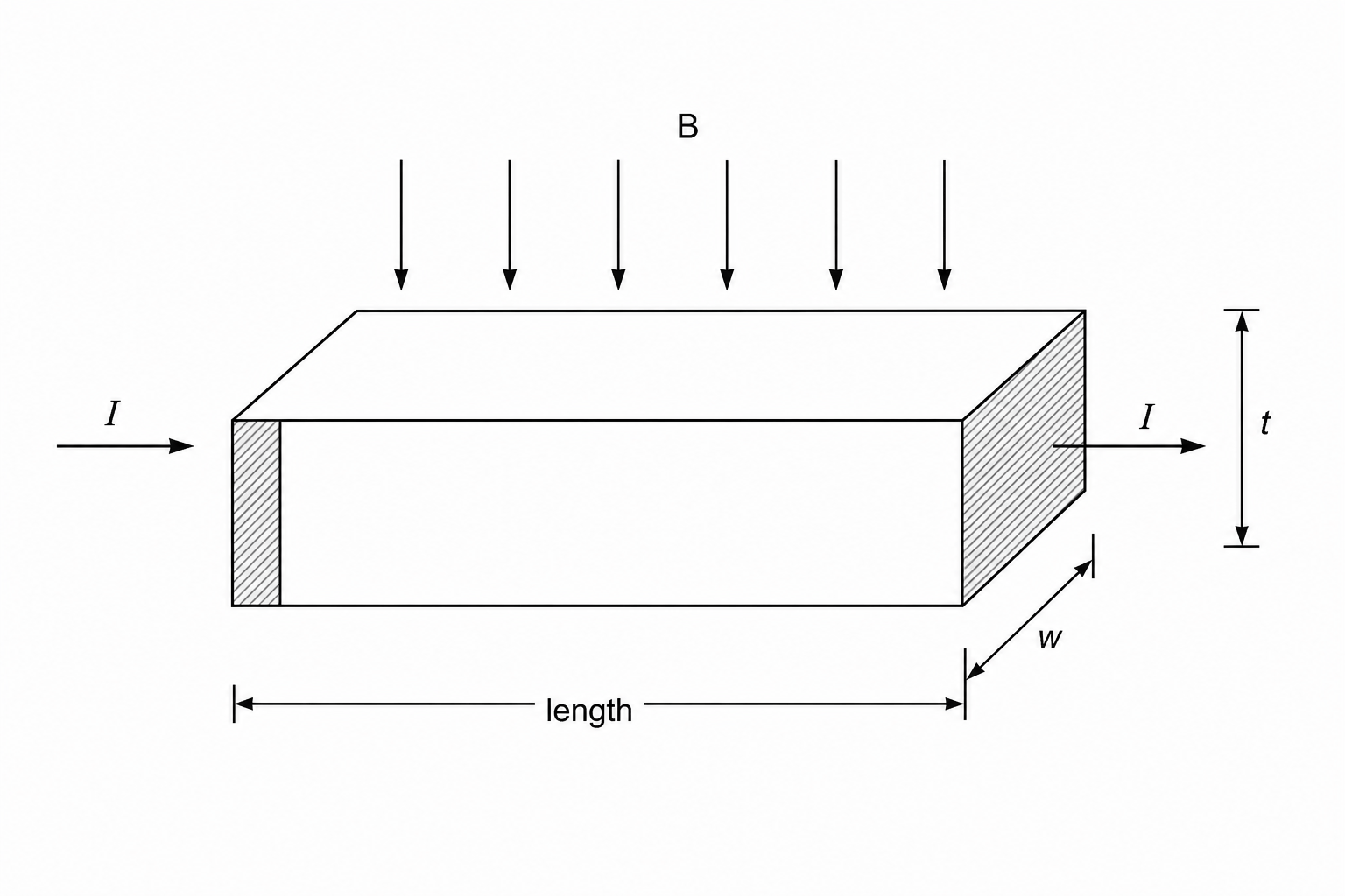
When the current is switched on, the moving holes are deflected by the magnetic field towards one of the side faces, where they accumulate. This accumulation creates a transverse electric field between the front and rear vertical faces, which are separated by the width www. Eventually, each charge carrier experiences equal and opposite electric and magnetic forces, resulting in a net transverse force of zero.
Write down the expressions for the electric force and the magnetic force acting on each charge carrier, and use these to show that the steady-state potential difference VVV between the front and rear faces is given by
V=BvwV = BvwV=Bvw
In a particular experiment, the slice has the following parameters:
- number of charge carriers per cubic metre, p=5.0×10²² m−3p = 5.0 \times 10^{22} \text{ m}^{-3}p=5.0×10²² m−3
- width, w=6.0 mmw = 6.0 \text{ mm}w=6.0 mm
- thickness, t=0.40 mmt = 0.40 \text{ mm}t=0.40 mm
- current, I=96 mAI = 96 \text{ mA}I=96 mA
- magnetic flux density, B=0.35 TB = 0.35 \text{ T}B=0.35 T
Use this data to calculate:
(i) the mean drift velocity vvv of the charge carriers within the semiconductor.
(ii) the potential difference VVV developed between the front and rear faces of the slice.
The semiconductor slice is mounted and used as a Hall probe. A cell is connected to maintain the constant current through the slice, and a voltmeter is connected across the front and rear faces to measure the Hall voltage.
A student intends to use this Hall probe to measure the weak magnetic flux density between the poles of a pair of slab magnets. The expected flux density is between 0.005 T0.005 \text{ T}0.005 T and 0.010 T0.010 \text{ T}0.010 T.
(i) Suggest, with a calculation, why this Hall probe is not a suitable instrument to measure the magnetic flux density in this range.
(ii) An alternative method to determine the magnetic flux density is to suspend a straight current-carrying wire between the poles of the magnets. Explain how the magnetic flux density BBB can be determined using this current-balance method, and discuss which experimental measurement introduces the greatest uncertainty in the calculated value of BBB.